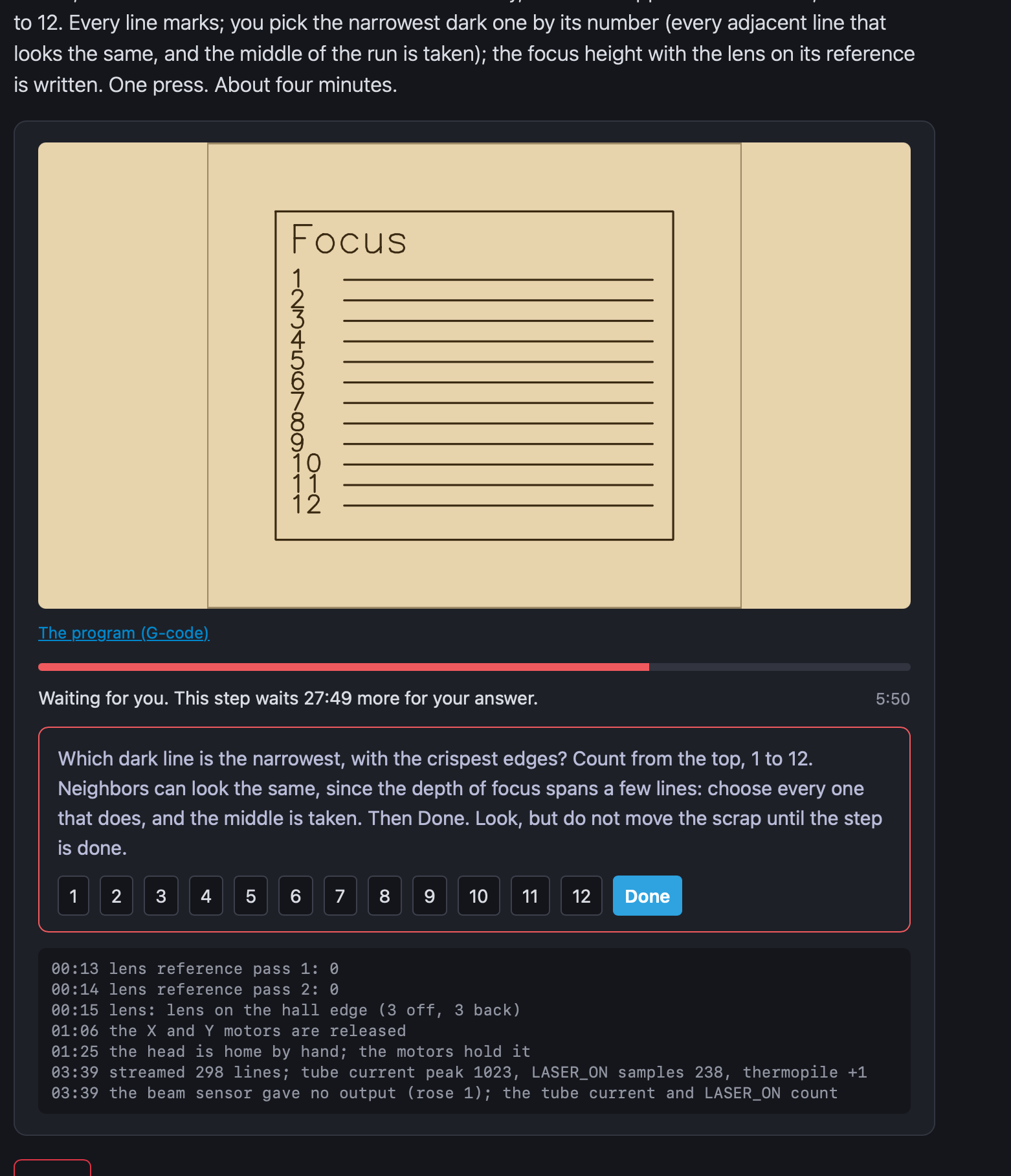
I moved this to a separate topic so it doesn’t get lost in release note discussions.
This is actually a complex issue that I consider far from resolved.
Before discussing the specifics of the issue your machine is encountering, let me give a bit of background about the flow detection mechanism. It’s long winded. If you are only interested in the next steps, skip to the end. 
FACTORY FLOW DETECTION
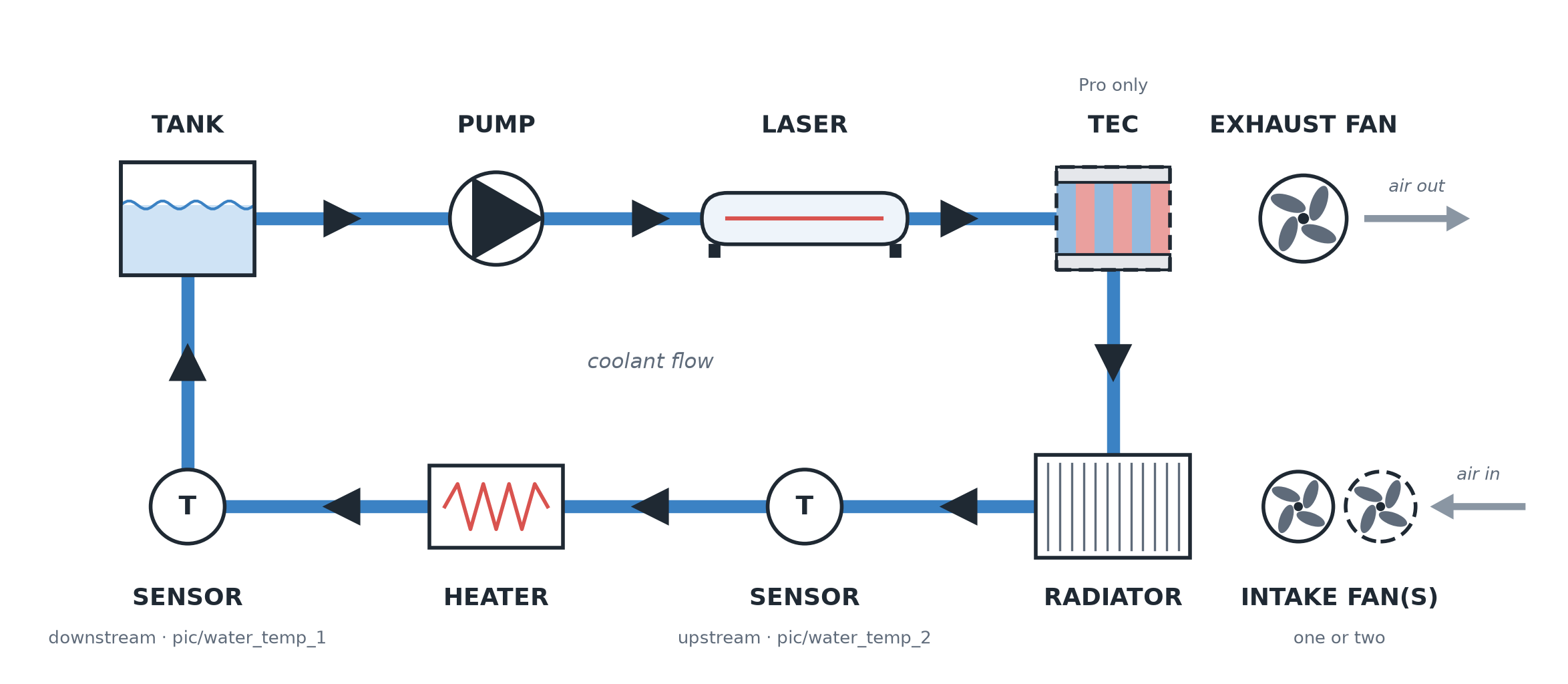
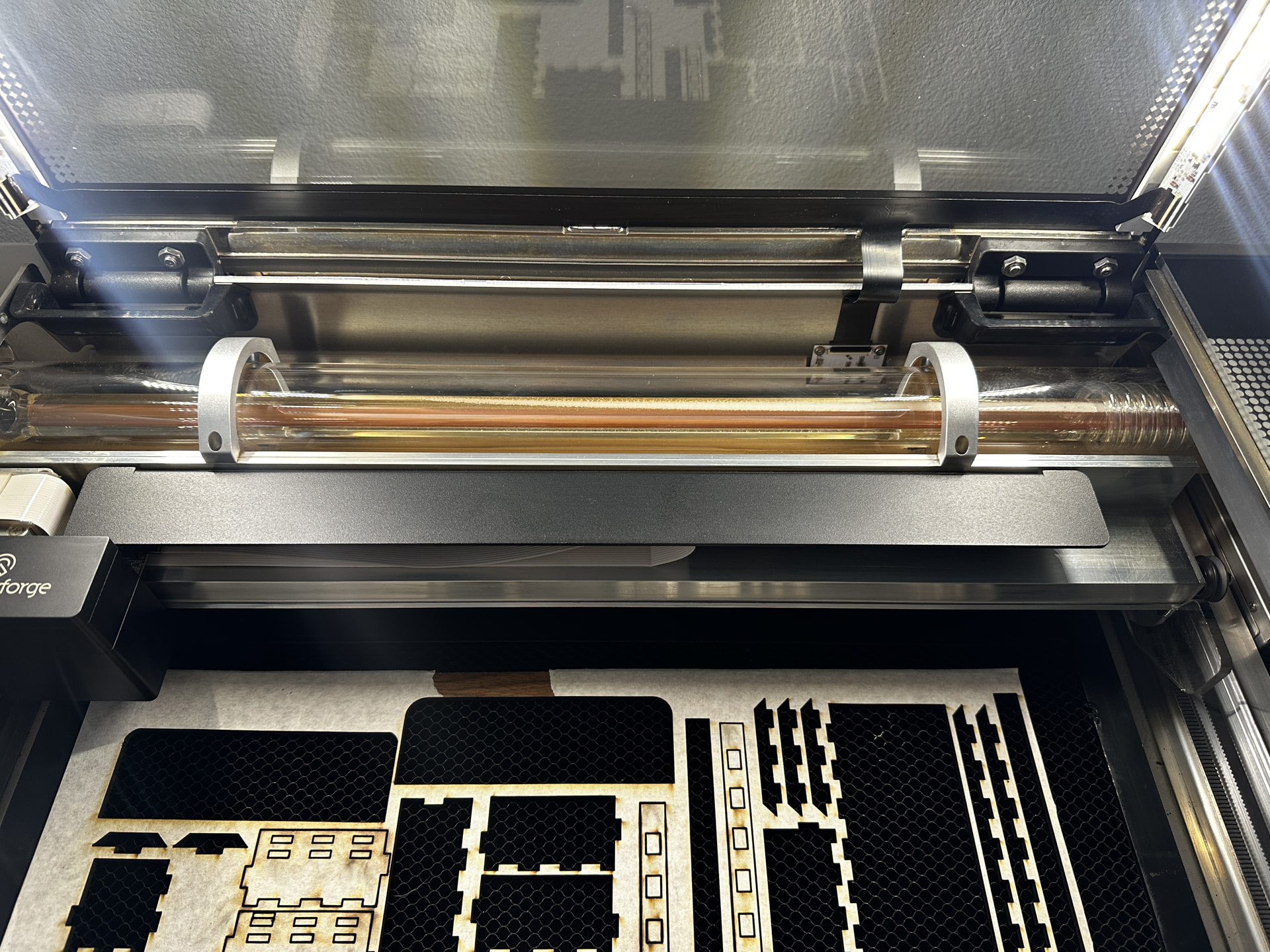
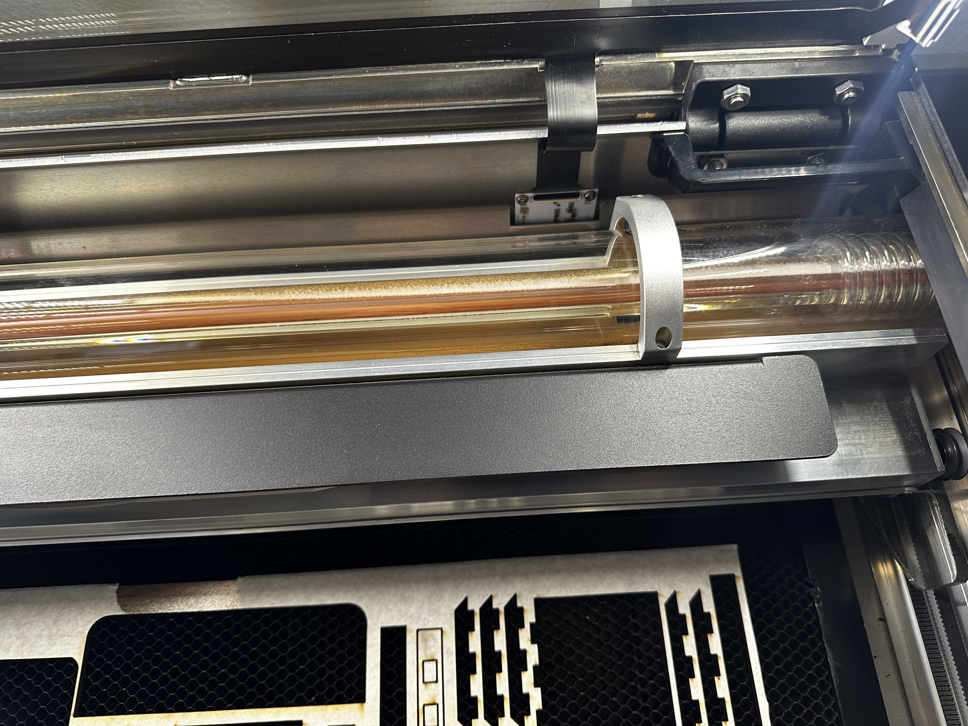
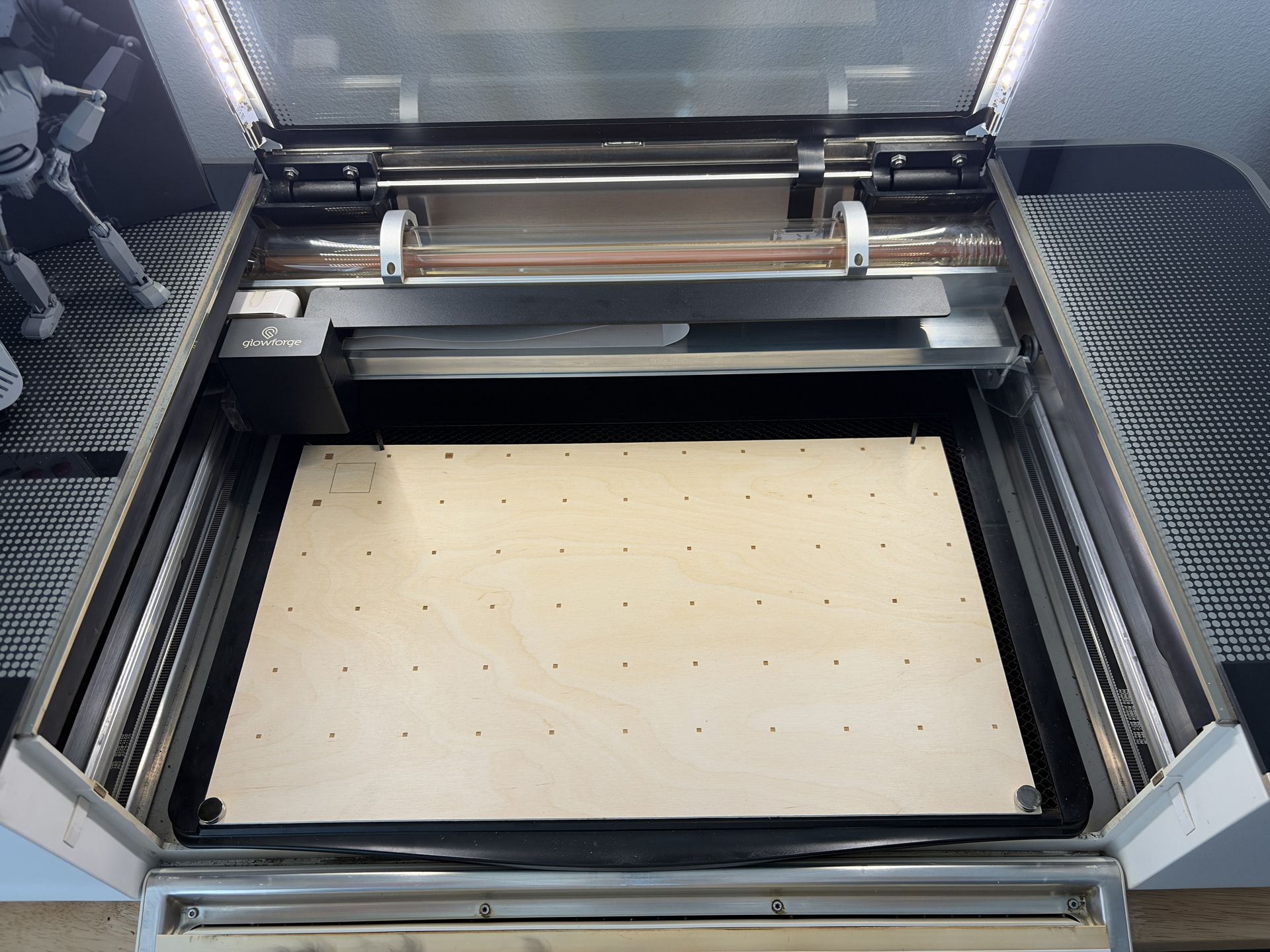
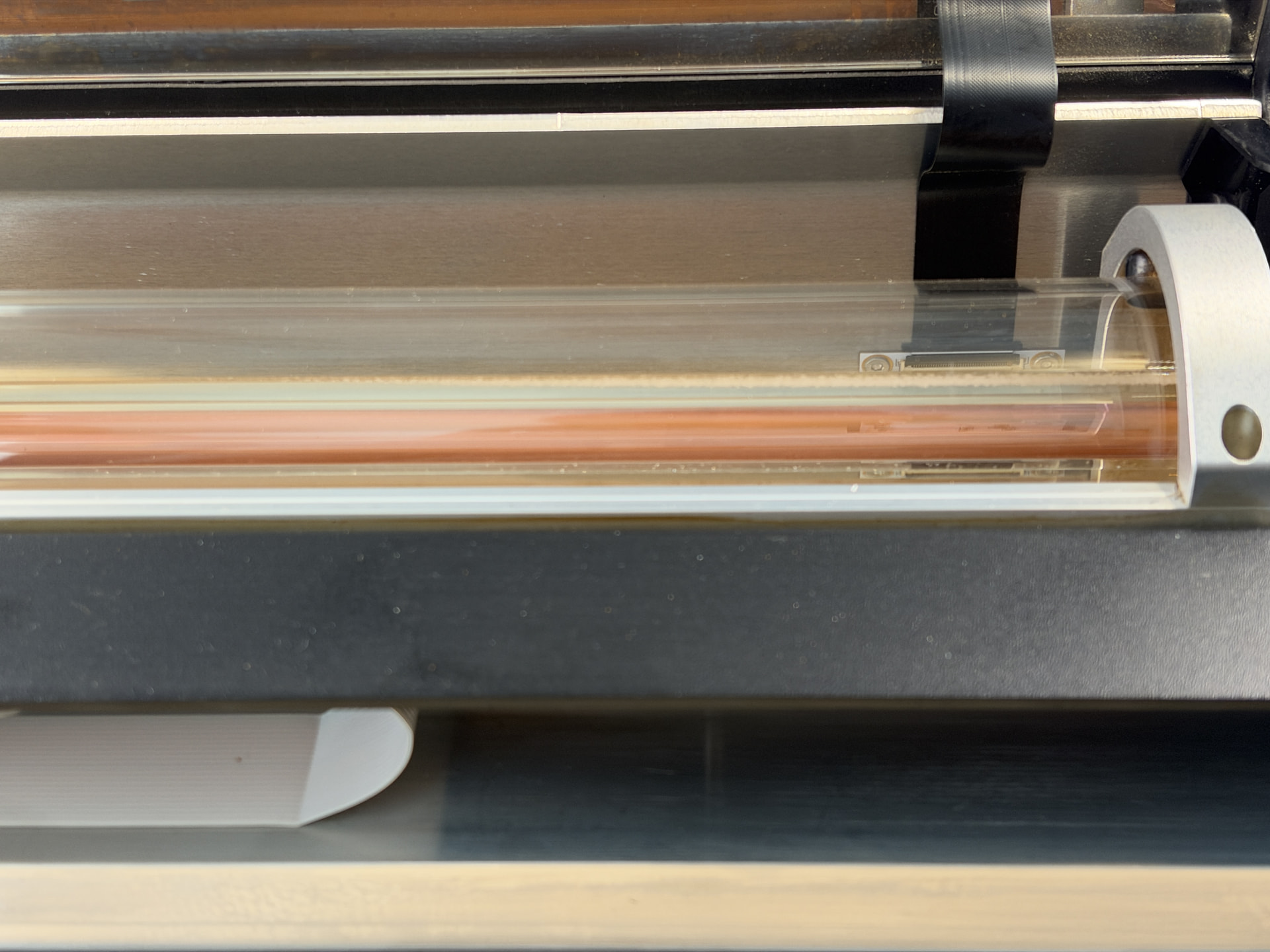
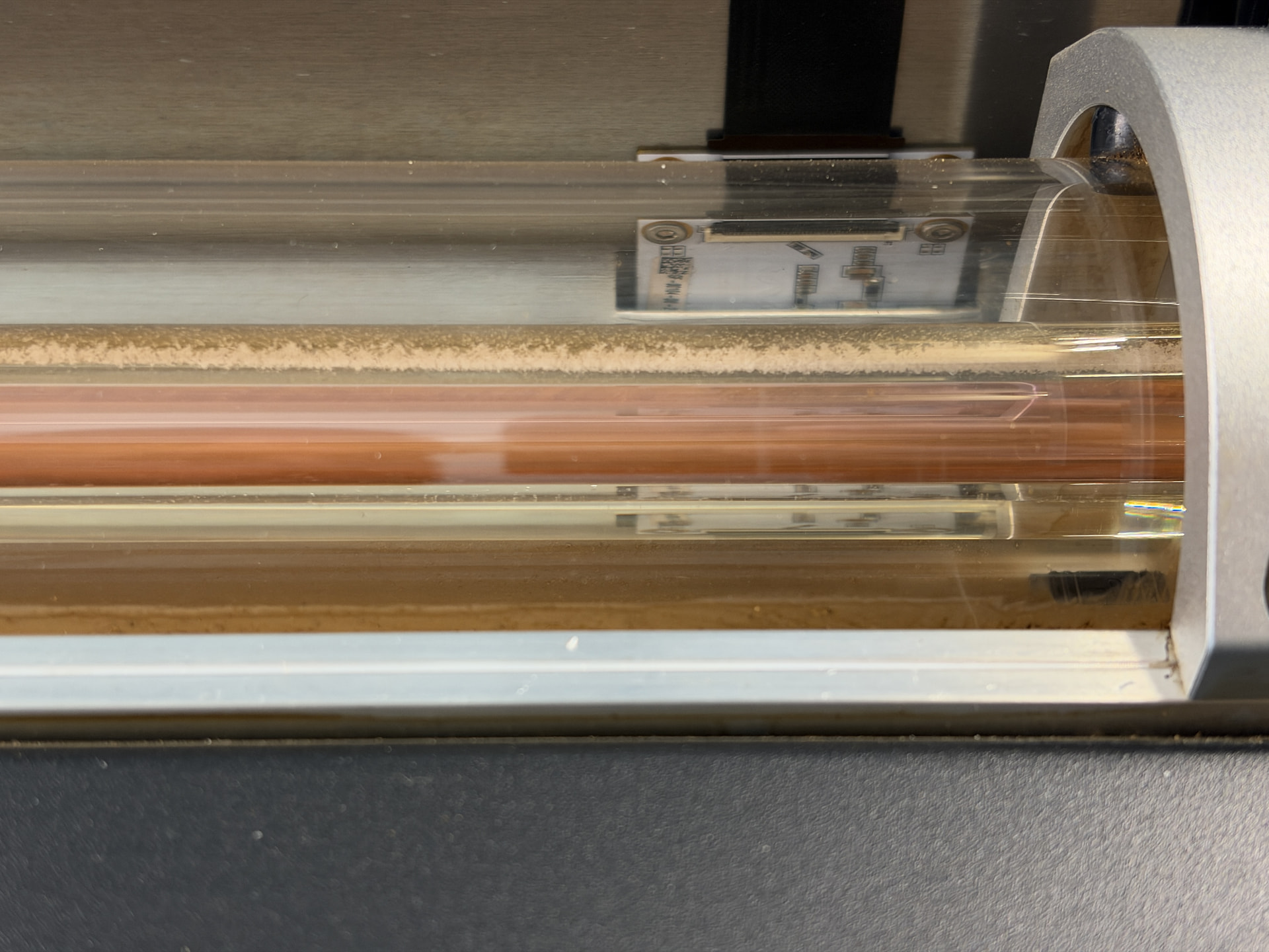
This is the cooling loop, common to all Basic/Plus/Pro models (at least as far as I have seen… I can’t rule out later production changes):
Short version: the factory firmware used to check coolant flow, but the firmware
never acted on what it found directly, and Glowforge removed the check in 2019. Since
then the machine watches only one coolant temperature, and nothing in the firmware notices a
stopped pump until the coolant gets too hot.
This comes from reading 27 factory firmware builds, from 1.1.2 (October 2017) to 2.6.0, along with job settings captured from the cloud service. I am certainly missing a few versions, so do not consider this analysis to be exhaustive.
The hardware
The coolant loop has a pump, two temperature sensors (thermistors), and a small in-line heater between them. A Pro also has a thermoelectric cooler (TEC). There is no flow sensor.
A heater between two temperature probes is the classic way to measure flow without a flow meter. You heat the water and watch how much the downstream probe rises. Moving water carries the heat away, and still water lets the probe cook. The hardware was clearly built for this.
Factory Firmware
The following is from binary analysis on the factory firmware images I have. Unless stated otherwise, the analysis is only on the firmware’s behavior, not how the cloud services respond to the telemetry stream.
October 2017: a flow check that only logs (1.1.2, 1.2.0)
The earliest builds ran a coolant state machine with:
- a temperature window,
- a sensor-offset check,
- a heater driven by a feedback loop.
It has a flow check, but all the check does is write “Flow is below threshold” to the log and carry on. A “flow failure” state exists in the code, but nothing can ever enter it. These builds also log the coolant temperature before and after each cut without comparing the two.
November 2017 to December 2018: a real flow check (1.2.1 to 1.9.0)
1.2.1 replaces the state machine with a heater-rise flow controller that measures flow:
- A feedback loop running ten times a second drives the heater to hold a target temperature rise across it.
- At startup it runs a pump test. With the pump off it waits for the rise to climb past a limit, then turns the pump on and waits for the rise to fall back, which shows the pump is moving water.
- During operation, a reading outside the expected band raises a “possible coolant flow error” alert and runs the test again. A test that does not finish within about 60 s raises “Coolant flow failure (broken pump)”. A feedback loop that stays off target for about 20 s raises a heater failure.
The faults stop nothing. In 1.6.0, which was checked in detail, all three are logged and reported to the cloud, but none pauses, aborts, or fails the job. The “cannot start print until coolant flow monitoring initializes” gate waits only for the controller to start up, never for a passing result.
The cloud likely never configured it. 156 job files were captured between August 2018 and March 2019, while this controller was in the firmware. None of them carries any of its settings: no target, no gains, no limits. So it ran on its built-in defaults, which set the target rise to 0 and the allowed error to zero width. Read literally, that cannot make a working check. The heater is held near off while the startup test waits for a rise that never comes, so the “broken pump” fault would fire about a minute after every boot. A settings push from the service outside a job could also have changed them, and these captures don’t show whether one ever did.
Cut jobs in this period carried a coolant window of 5 to 31 C while cutting and 7 to 29 C during warm-up.
February 2019: the faults are disconnected (1.9.2)
The controller is unchanged, but its three faults become warning lines in the log. A failed flow check is now just a log entry.
April 2019 on: temperature only (1.10.1 through 2.6.0)
1.10.1 removes the flow controller, and every later release is the same:
- Temperature only. The firmware watches a single thermistor against a minimum and a maximum for each machine phase (idle, warm-up, run), with a small margin before an alert clears. A plain alert pauses the job, and the harder limits fail the machine. The cloud sends the window with each job: 5 to 33 C while cutting, 7 to 31 C during warm-up, 10 to 50 C at idle.
- An empty shell is left behind. The flow controller’s eighteen settings still exist, but the code has no timer and does no arithmetic, so nothing runs. Its three fault codes are still defined, and nothing raises them. The cloud has never been seen sending its settings: only one of the eighteen has ever shown up in a captured job, and never the target, gains, or limits a check would need.
- The heater gets a fixed value at phase changes and nothing else. Nothing reads back what it does. Whether that value is ever above zero on a stock machine has not been confirmed.
- A stopped pump is caught only by its consequence: the coolant has to get hot enough to leave the window. A stopped exhaust fan is caught the same way.
July 2022 on: data for the cloud (2.5.0 and later)
2.5.0 adds a thermal report. During each print the machine records coolant temperature, laser supply readings, and lid IR on one clock, then uploads them to Glowforge afterward. The machine itself decides nothing from this data. Any judgment, such as whether the coolant warmed as it should have, happens on Glowforge’s servers, after the print.
Through every version
No factory version checks on the machine that the coolant warms up when the laser fires. The flow controller of 2017–2019 measured the rise across its own heater, not the rise the laser caused.
Caveats
- The captures come from a machine without a TEC. The firmware turns the TEC on above a threshold; on a machine without one, that threshold is set to a value the coolant can never reach. What a Pro actually uses is unknown.
- Which of the two temperature families the current monitor actually compares against (raw sensor counts or degrees) is still open. The cloud sends a real window only in degrees, and leaves the raw-count window wide open.
FORGEFIRM FLOW DETECTION
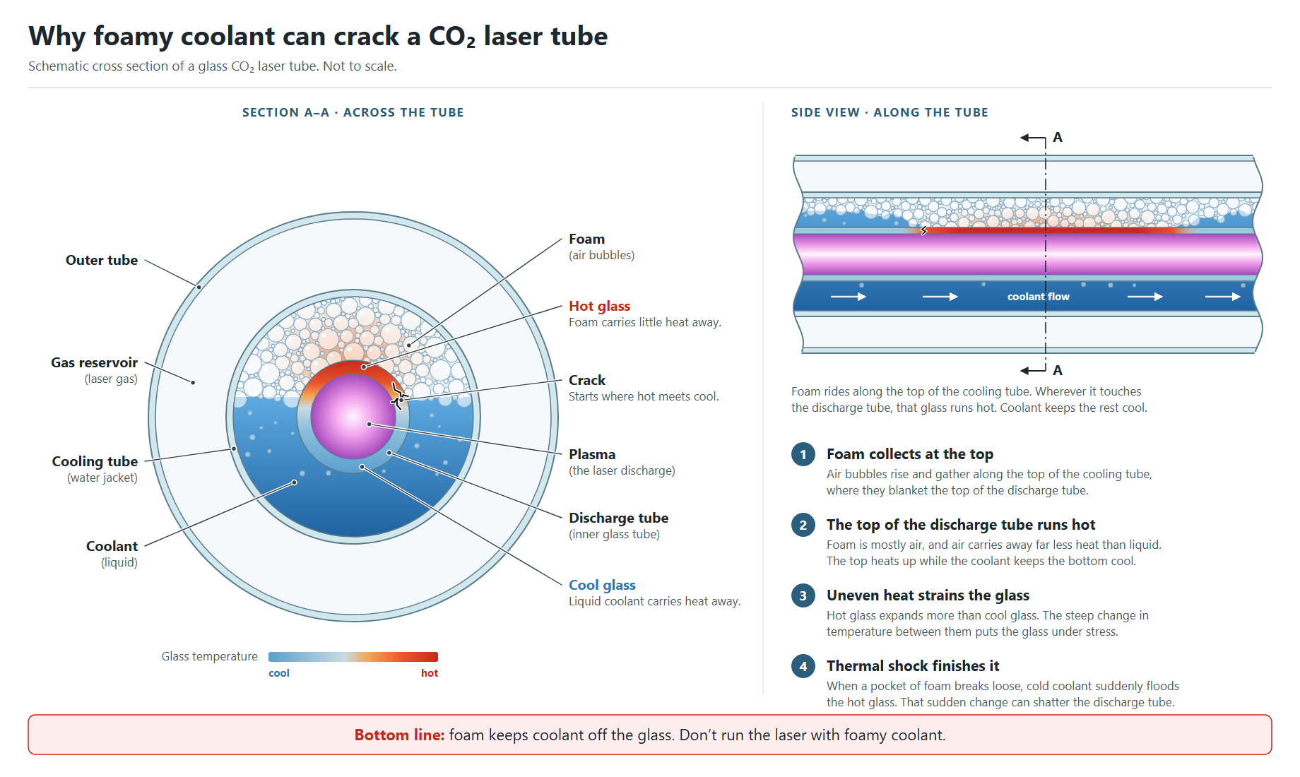
Running a CO2 laser without adequate cooling can shorten tube life and, in the case of no flow, cause catastrophic damage to the tube. Avoiding damage due to coolant issues naturally seems like a feature ForgeFIRM users would desire, so I decided to see if the flow detection hardware can be made to work.
Short version: ForgeFIRM uses the in-line heater the way the hardware was built for. While a job runs, it switches the heater on for 50 seconds every few minutes and watches how far the downstream sensor climbs. Moving coolant carries the heat away, while a stopped loop lets the sensor cook. A high reading pauses the job and checks again, and a second high reading blocks the laser. It works, but it adds heat, it sends warm coolant into the tube, and machines turn out to differ more than the design assumed. It’s a problematic and temporary solution.
Measured values below come from my bench machine, a late-2017 Basic, unless another machine is named.
How it currently works
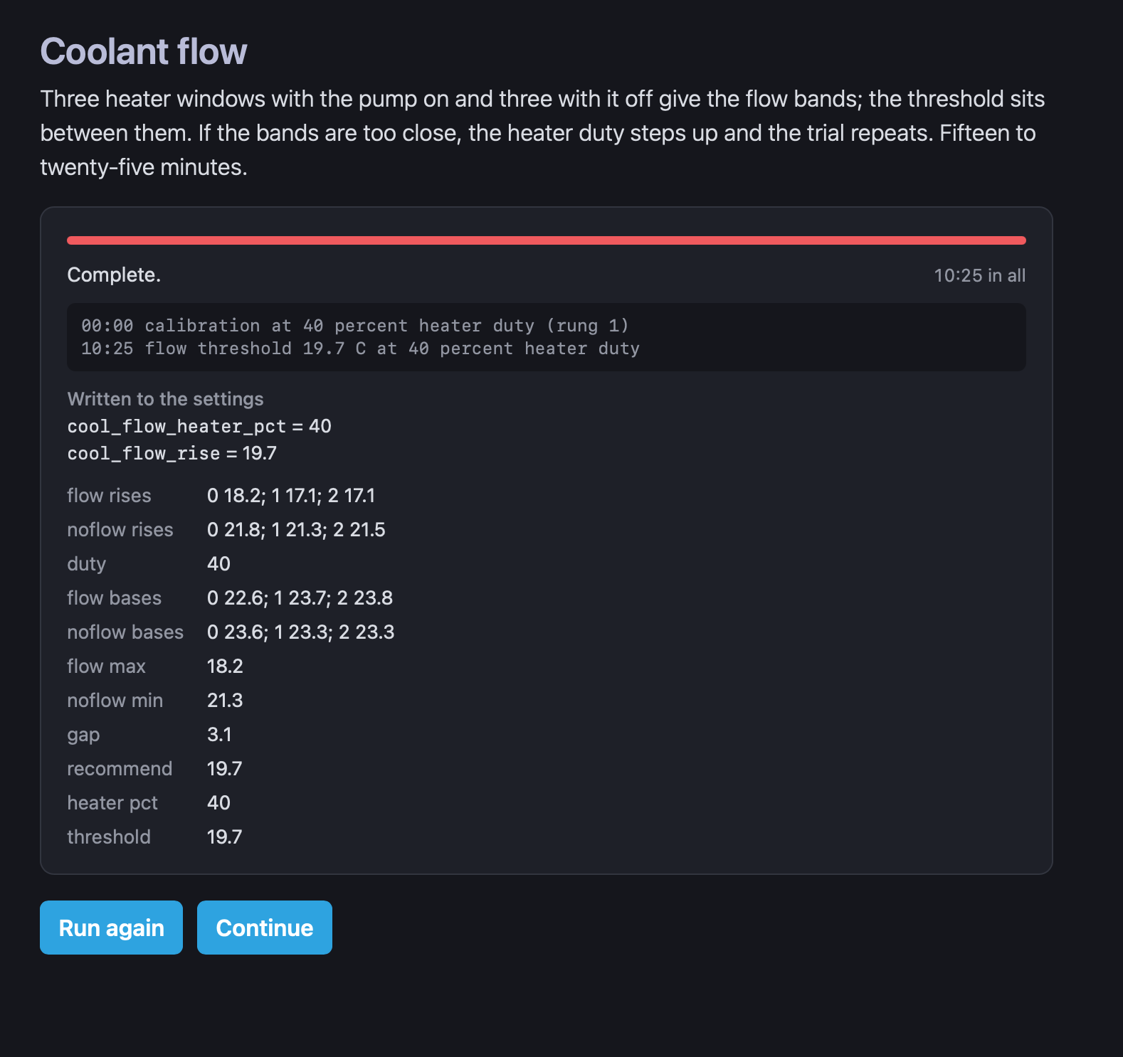
- The check. The heater runs at 40 percent for 50 s. The rise of the downstream sensor is compared with a threshold of the machine’s own. The shipped default is 14.4 C.
- When it runs. It runs only during a job; the heater is off at idle. A check is requested when a job starts, and the next one 150 s after each check ends. A check starts only once the loop has settled: the two sensors agree within 1.5 C and the downstream reading has stopped drifting.
- How it reads. The rise is taken from averages, never single samples, and the tube’s own heat during the window is estimated from its current and subtracted.
- What a high reading does. The first one is a suspicion: the job pauses and the check runs again as soon as the loop settles. A clean re-check resumes the job. A second high reading is a fault, and the laser is blocked until the operator deals with it. A suspicion that can’t be resolved within 8 minutes becomes a fault, and three cleared suspicions in one job earn a “check your coolant” warning.
- Calibration at setup (required).
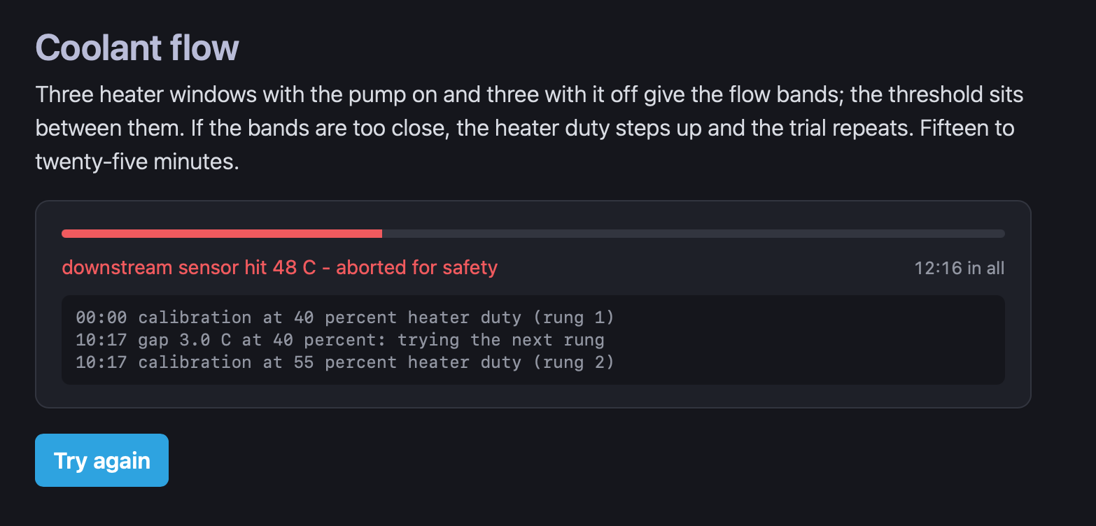
- Setup runs three heater windows with the pump on and three with it off, and puts the threshold midway between the two groups.
- If the groups are less than 3 C apart, it raises the heater duty to 55, then 70 percent, and tries again.
- Any window stops early if the downstream sensor reaches 48 C.
Why it’s built this way
- Why a heater check at all. There is no flow sensor. Coolant temperature alone only tracks a loop that is circulating, and the laser’s own heat is no signal: a light engrave may add none. Heating the water between the two sensors is the only way to ask the loop whether it is moving.
- Why the rise, not the difference between the sensors. From cold, flowing coolant levels off about 10.5 C up at 30 percent, while stopped coolant passes 16 C and keeps climbing. That is a margin of about 6 C, against about 2 C for the difference between the sensors. On the bench, a check based on the difference missed a stopped pump.
- Why 40 percent. Below about 40 percent, still coolant sheds the heat by natural convection well enough to look like flow. At 30 percent, three of five stopped-pump trials looked healthier than a working pump. 40 percent was the lowest duty where the two separated every time, across a 60-run test matrix.
- Why 50 seconds, and why the heater is off between checks. The reading levels off by about 30 s. Running longer, or leaving the heater on, only warms the loop: an always-on heater added about 1.5 C within minutes.
- Why 14.4 C. It sits midway between the bench’s worst flowing reading (12.75 C) and its lowest stopped reading (16.04 C).
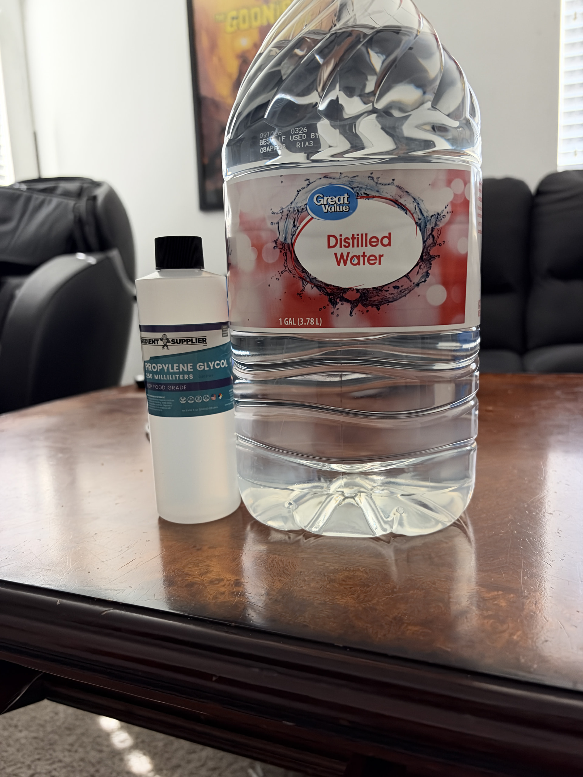
- Why every machine is calibrated. An early Pro rose 15.8 to 16.2 C with flow and 20.5 to 20.9 C without. The bench default sits below that machine’s flowing reading, so it would have flagged every job as a stopped pump.
- Why wait for a settled loop. A baseline taken while the loop is still cooling gives a wrong answer either way. On the bench it once reported flow with the pump stopped: a rise of 11.2 C from a loop cooling down from 48 C.
- Why averages. The run fans shift both sensor readings by about a degree, so two single samples can differ by a degree with no heat behind them.
- Why subtract the tube’s heat. A window with the tube lit the whole time adds about 1.5 C to the rise, nearly the whole 1.6 C safety margin.
- Why a suspicion before a fault. Air in the lines comes and goes, especially after the pump has been stopped and started, and it clears on its own within minutes. A loop that has really stopped can’t pass a settled re-check.
- Why every 150 s. Short of the coolant overheating, a pump that stops mid-job shows up nowhere else. The interval is a trade between how fast that’s caught and how much heat the checks add.
The downfalls
It adds heat to the loop
- Each check warms the whole loop by about 0.8 C on the bench, and during a job the heater runs 50 s out of every 3 to 4 minutes.
- On the bench the cut-profile fans remove that and more, so a long job still comes out cooler. That was measured on one machine with spare cooling.
- A hot room, a one-fan machine, or a loop that already runs warm may not have the margin, and the checks then push the coolant toward its ceiling.
- Calibration is worse: 15 to 25 minutes of repeated heating, at up to 70 percent duty when the first attempt doesn’t separate.
It sends warm slugs of coolant through the tube
- The heater sits on the line from the radiator back to the tank. The water it warms goes through the tank and the pump into the laser tube before it reaches the radiator again.
- During a job, every check sends a slug of warmed coolant into a tube that is cutting, and a CO2 tube’s output falls as its coolant warms. The size of that slug at the tube (after mixing in the tank) and its effect on cut power have not been measured.
- The slugs also keep circulating. They show up on the sensors when they come back around, which is one reason checks have to wait for a settled loop.
- Calibration’s pump-off windows are harsher. The still water at the heater can reach 48 C, and when the pump restarts that pocket goes through the tube in one piece. The laser is locked during calibration, but the heat still goes into the loop. On one machine the upstream sensor read 33 C a second after a window stopped, enough to trip the over-temperature hold.
Machines differ more than the design assumed
The operating point, the 3 C minimum gap, the duty ladder, the 48 C cap, the settling rules and the tube-heat correction all come from one machine. Calibration tunes only the threshold and the duty. The flowing and stopped readings seen so far, all at 40 percent:
| Machine |
Pump on |
Pump off |
| Bench (late-2017 Basic) |
12.75 C or less |
16.04 C or more |
| Early Pro |
15.8 to 16.2 C |
20.5 to 20.9 C |
| Your Pro |
17.5 to 19.2 C |
21.5 to 23.4 C |
- Your Pro can’t finish setup. Its groups are about 4 C apart on average, but each spreads about 1.8 C (the early Pro’s spread 0.4 C), so the closest pair is only 2.6 to 3.0 C apart.
- Raising the duty can’t help it. At 55 percent the downstream sensor reaches the 48 C cap even with the pump running, so the higher steps can only stop for safety. A loop that runs this hot has no headroom for the very step meant to separate it.
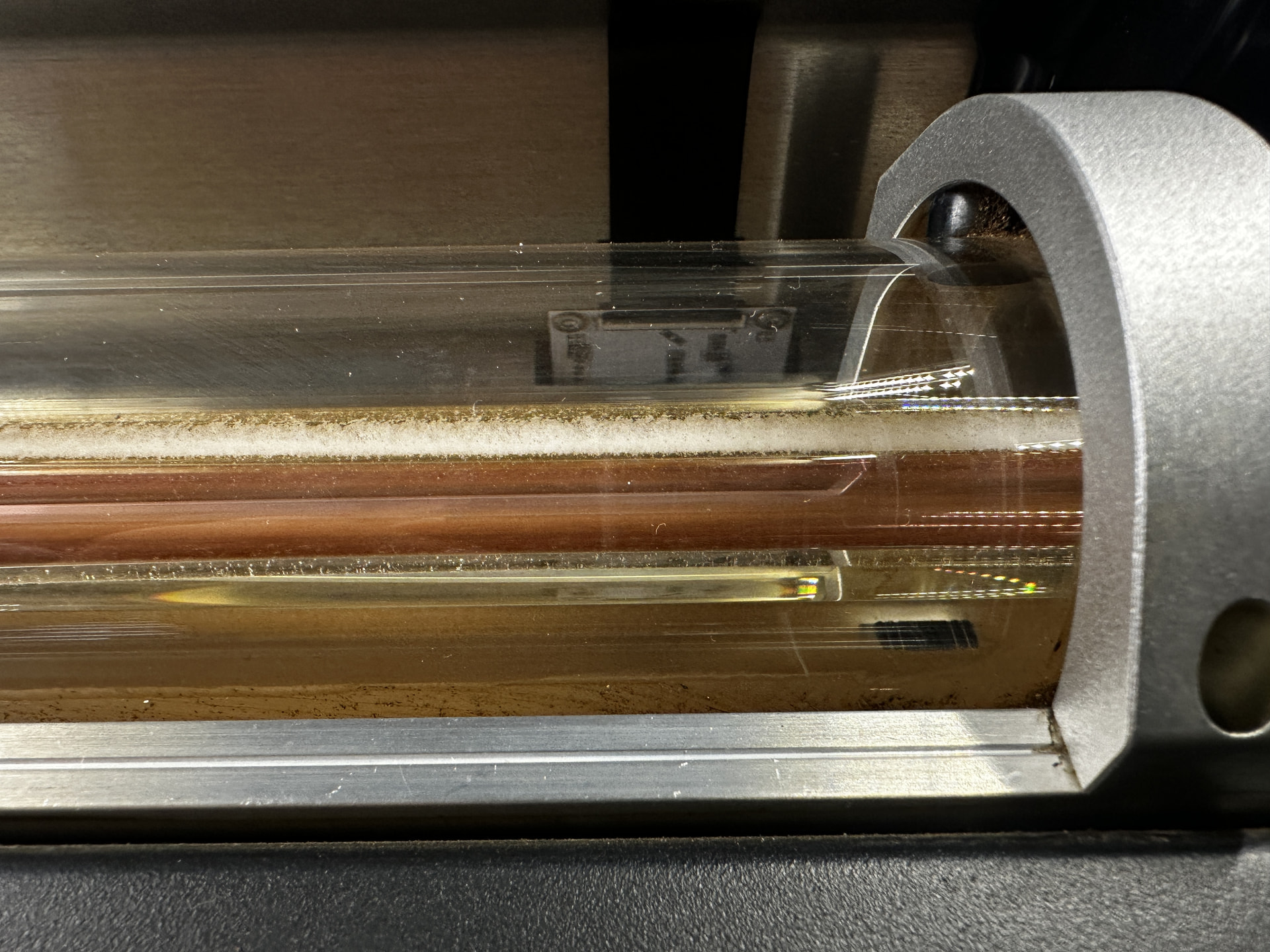
- Why your Pro runs hotter is unknown. The heater or sensor assembly, the coolant mix, the flow rate (pump wear, plumbing, the extra cooler block on a Pro, air in the lines) and sensor tolerance are all candidates. A one-number threshold can’t tell those apart.
- The sensors carry electrical shifts that vary by machine. The air-assist fan shifts both readings while it runs, and the correction for it has to be calibrated on each machine. With the tube lit, the readings also toggle by 0.6 to 1.1 C.
- The calibration is noisier than the check it sets up. Its trials read single samples, while the check during a job reads averages. That adds scatter exactly where a narrow machine can’t afford it.
Other limits
- It is periodic, not continuous. A pump that stops right after a clean check isn’t flagged until the next one, about 4 minutes later, or longer when the loop is slow to settle. The coolant temperature ceiling covers the gap.
- A job doesn’t wait for the first check to pass. The first verdict lands a minute or more after the job starts.
- Calibration stops and starts the pump repeatedly. Up to nine times, and a pump stop and start is a known way to trap air in the loop.
- The tube-heat correction is the bench’s. No setup step measures it on each machine.
WHAT YOU ENCOUNTERED
On a fresh install of ForgeFIRM 0.0.9, you couldn’t get past setup’s Coolant flow step, which is required before the machine will run a job. You tried three times with the same result. The step heats the sensor board three times with the pump on and three times with it off, and it needs at least 3 C between the two sets of readings to set a threshold. At 40 percent heater power this machine read:
|
Pump on |
Pump off |
Closest pair |
| Your Pro |
17.5–19.2 C |
21.5–23.4 C |
2.6 C, and just under 3.0 C |
| Another Pro |
15.8–16.2 C |
20.5–20.9 C |
4.3 C |
| My Basic |
12.75 C or less |
16.04 C or more |
3.3 C |
The two sets were about 4 C apart on average, which would be enough. But each set spread over about 1.8 C, against 0.4 C on the early Pro, and that scatter pushed the closest pair under the 3 C minimum.
When the readings are too close, setup raises the heater to 55 percent and tries again. On this machine that can’t work. At 55 percent the downstream sensor reached the 48 C safety limit in under two minutes, even in a pump-on window, so each attempt stopped for safety. On the first attempt the limit was reached at 40 percent, during a pump-off window. A second later the upstream sensor read 33 C, which held the machine for over-temperature for a few seconds. In 0.0.9 there is no way around the step.
What the data suggests
The board has a heater between two sensors, and the useful signal is how much of the heater’s warming reaches the upstream sensor.
- With good flow, almost none should; on our bench it rises 0.1 to 1.6 C.
- On your Pro the upstream sensor warmed roughly 3 to 5 C even with the pump running. That is closer to what my basic shows with the pump off.
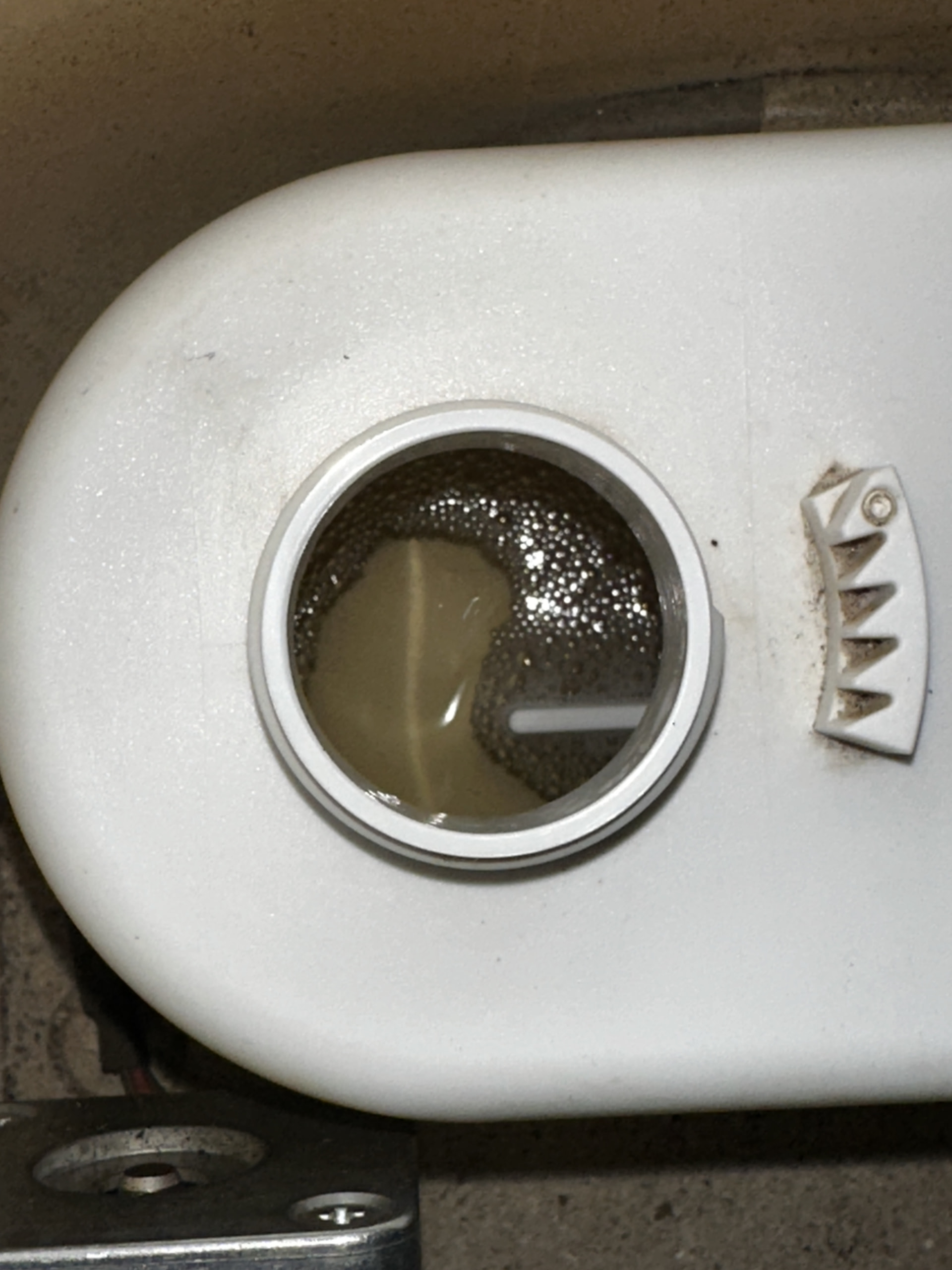
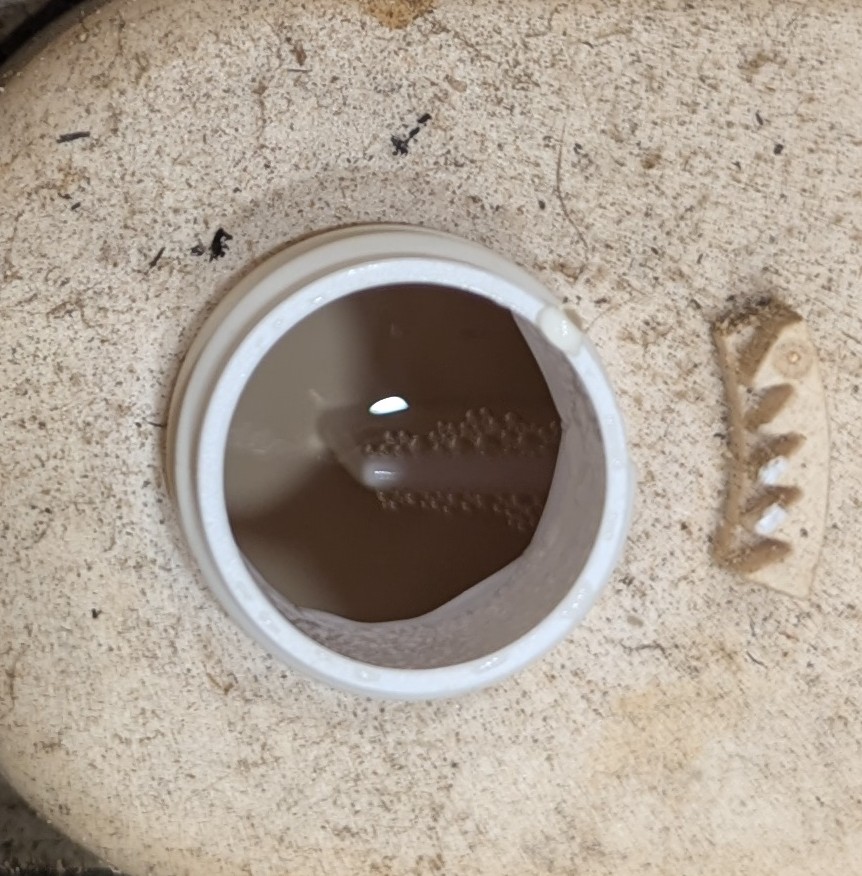
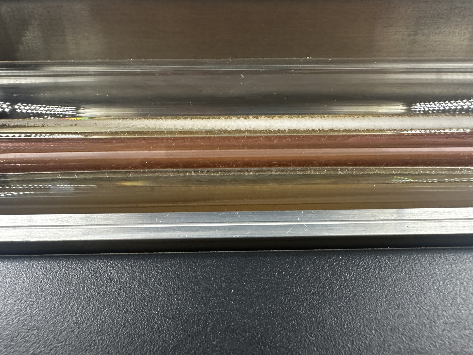
That points to weak flow past the sensor board, perhaps air in the loop, which would fit the bubbles. It is an indication only: it is worked out from single end readings, not a direct measurement. A different heater or sensor board, or a different coolant mix, could also play a part. The TEC was not a factor; it stays off during setup.
What it showed about ForgeFIRM’s check
- It reads only the downstream sensor. It judges that sensor’s rise, not the comparison between upstream and downstream that the board is built for. That makes it sensitive to every way machines differ.
- Calibrating a single number can treat a real flow problem as normal. If setup had found a threshold on this machine, it would have accepted a loop that may not be moving much coolant.
- Raising the heater power is the wrong fallback for a loop that already reads hot. It runs into the safety limit before it can help.
- Setup’s own trials are noisier than the check they calibrate. They read single samples, while the check during a job reads averages.
Next steps
Short term: adjust the existing calibration
The goal is to let setup finish on machines like this one without loosening any safety margin.
- Read the trials from averages, the way the check during a job does. That should cut the scatter that kept the closest pair under 3 C. Your machine missed by less than a tenth of a degree on one attempt.
- Stop raising the heater on a loop that already reads hot. When the 40 percent readings show that a higher setting would run into the 48 C limit, repeat at 40 percent instead of stepping up to 55 and 70.
- Record each trial’s starting temperature, so a warm or slow-settling loop shows up in the log.
Long term: a better way to read flow
- Use both sensors. Judge flow by how much of the heater’s warming reaches the upstream sensor, as a share of what the downstream sensor sees. That is the comparison the sensor board is built for. On our bench it already separates good flow from no flow cleanly at 40 percent, within 30 seconds.
- Find out what “pump off” really means. With the pump stopped, my basic still carries heat toward the downstream sensor, possibly because the heater’s own warmth keeps a slow flow going around the loop. The slight upward slant of the sensor board as it goes toward the reservoir my play a role in this.
- Try less heat. Repeat the bench measurements at lower heater power, with averaged readings and the cool-down after the heater recorded. Less heat means smaller warm slugs through the tube and less load on the cooling.
- Collect readings from more machines, before settling on a new design, so it isn’t tuned to one machine again. Looking to all beta testers to submit logs, please. To date, I only have logs from two machines and they are from before they completed setup.
I’ll try to get the short term solution released today or tomorrow.