U27,U28, and U29 are rail-to-rail ESD protection devices.
A handy reference for this type of adventure is the OpenGlow schematic. It was designed as a drop-in replacement that is connector-for-connector/pin-for-pin compatible with the OEM control board.
From the OpenGlow schematic (NOTE: I used a slightly different ESD/EMI protection scheme):
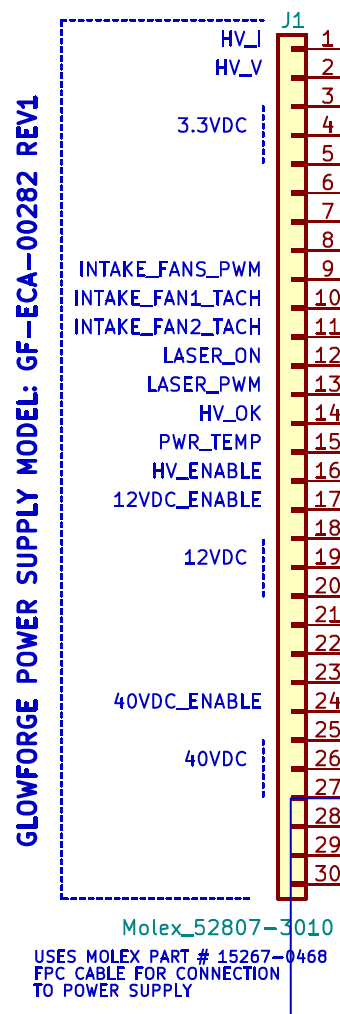
There you can see the pin assignments for the power supply connector (J1).
U28 has the following connections:
| PIN | Connection | Description |
|---|---|---|
| U28-1 | J1-1 | HV Current Feedback |
| U28-2 | GND | |
| U28-3 | J1-10 | Intake Fan #1 Tachometer |
| U28-4 | J1-9 | Intake Fans PWM Out |
| U28-5 | 3.3VDC | |
| U28-6 | J1-2 | HV Voltage Feedback |
As this is strictly a passive protective component, and assuming there are no other problems in the system, the donor board will still operate fine without that part. However, as you have experienced, ESD spikes do occur, and those devices do a great job of protecting the signal lines (often at their own expense) - preventing damage to devices that are much harder to replace (like the microprocessor).
A suitable replacement would be something along the lines of this:
As to J4, you can also find the part number for that on the OpenGlow schematic:
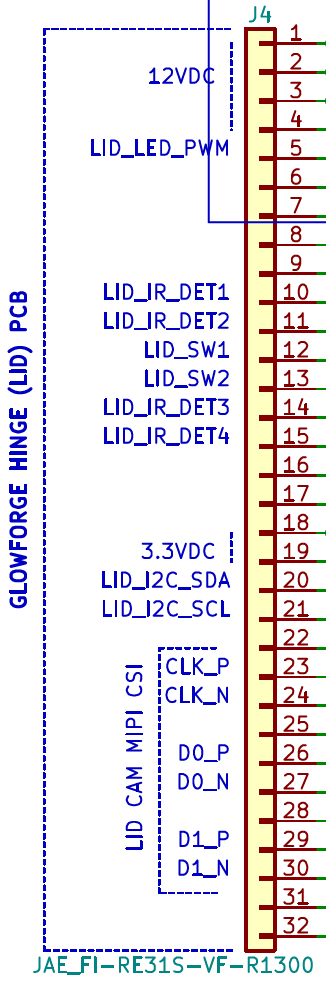
It is made by Japan Aviation Electronics, part number F1-RE31S-VF-R1300.