Power modulation not working

Hi everyone. I just took possession of an out-of-warranty Glowforge Plus. Fired it up, did a quick test on cardboard and everything seemed great. Grabbed some popsicle sticks to tinker with and that’s when I realized my issue. For any operation (engraving, scoring, etc), there is no difference in the applied power between a power setting of 1 and a power setting of 100. Always cuts the same depth (about 0.030") at maximum speed. I found another user with the same problem in the GF community and they ended up having to send their GF back for repair. I’ve been quoted $400-1000 for repair plus shipping and the $250 for the box mine didn’t come with.

I’m an electrical engineer by trade and I’m confident that I could probe around and figure out where the issue is, but I’m hoping the expertise in here could provide a head start. I searched through the topics on here and didn’t find anyone with my problem, but the “Laser not firing” topic appears to have some good troubleshooting info. I’m hoping to find a pinout of the power supply so I can at least see if the laser current signal is getting to it before digging deeper. Any advice?

Some pics


The text shown was cut on a popsicle stick for testing. The number
corresponds to the engrave power setting used, all were performed at
1000 speed and 225 LPI. There is no discernible difference between the
settings.

The square around the “10” was a score performed at 500/1 in a single
pass. It appears to be as deep as the engraved letters.


I found a piece of 1/4" thick maple plywood in my workshop and did a quick test with three squares, scoring at 1, 50, and 100% power, all at 500 speed, overlapping the edge of the board so that the depth of the score could be clearly seen. They are all the same depth.

Did a bit more digging. Looking at the information given by @ScottW514 in this thread, test point B2C is the “HV PWM”. Measuring this, I can indeed see the control board attempting to adjust the laser power. Following it through to the connector, this pin appears to connect to pin 13 of the ribbon cable going to the power supply (just found the wiki and confirmed this matches what Scott found). I removed and re-seated my ribbon cable and have confirmed that there is continuity all the way through to the power supply end.

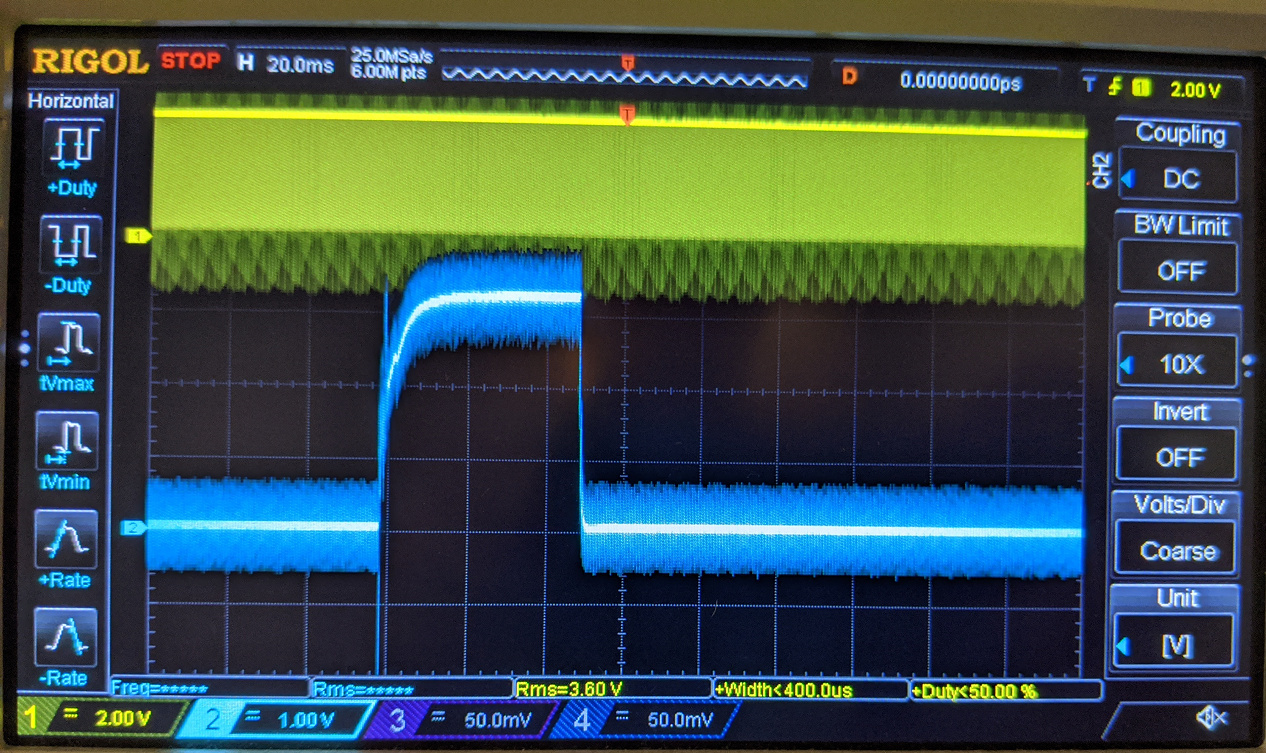
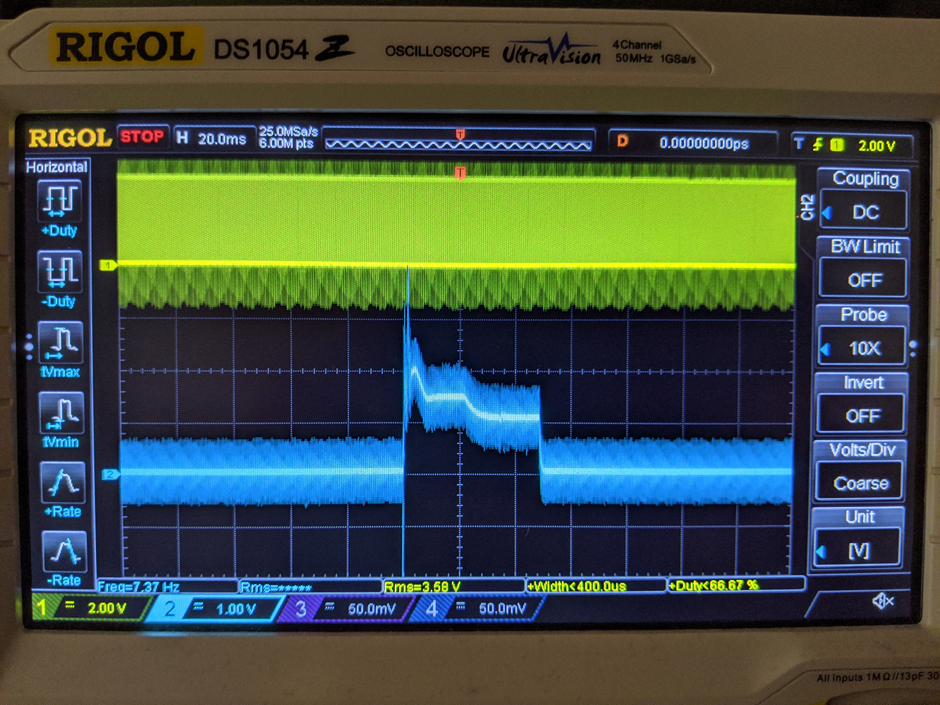
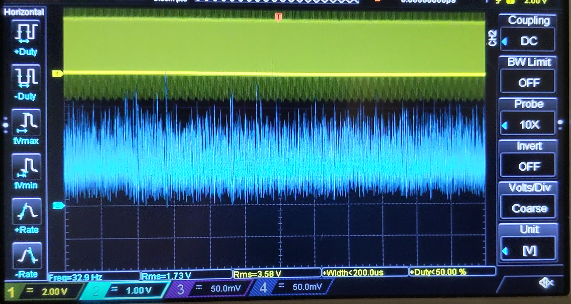
Looking even closer, I connected to B2F to observe the analog feedback of laser current. I performed a number of scores at various power levels and plotted the measured duty cycle and voltage corresponding to HV_Current (after settling, there is some initial overshoot). It appears that the HV current and duty cycle track each-other linearly from 100% down to about 5%. Below 5% the power supply current regulation appears to fall apart, turning into what is hopefully dithering but with an RMS value around 1.4-1.7V (depending on zoom level on the scope). I see this continuously at 1%, and intermittently at 3%. 5% power appears to be the lowest value that the power supply can regulate reliably.

HV_Current at 100% power

HV_Current at 5% power

HV_Current at 1% power

Plot. HV_PWM is in % duty cycle measured at B2C and HV_Current is in Volts B2F.
image

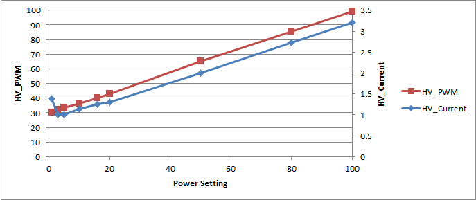
So it looks like the PWM ranges from 30-99% as the power setting ranges from 1-100%. I’m assume that this is likely due to the minimum power required to make the laser “lase”, but I’m not sure. Does this mesh with the experience of others who have measured their units in action?

Overall, it appears that my power supply is working as expected. Assuming that 30% actually is the lowest power setting, my control board is also working as expected. So now I’m confused as to why I’m struggling to varying depth/intensity when I run engraves, scores, and the like. How come engraving a square on plywood with a power level of 1%, speed of 1000, and LPI of 225 results in a pocket 0.56mm deep, but power level 100%, speed of 1000, and LPI of 225 results in a pocket 0.96mm deep? I would expect that a power level of 1% at speed of 1000 would barely mark the surface. I can’t think of any other way to reduce the amount of energy delivered. Any thoughts? Am I doing something wrong?

2 Likes

It appears that I may have had incorrect expectations for what results I would get out of engrave and score on wood when using vector graphics. When using a rastor image, I was able to mark so faintly that the image was only visible when viewed at just the right angle. So it appears that my problem was user error/incomplete understanding of the settings after all. Oh well, hopefully the power setting vs current graph is useful to someone :wink:

1 Like

Quite an impressive diagnostic effort! I look forward to your future explorations on this machine!

Your observations on the PWM duty cycle and GUI power setting are close to what I have observed. I do think there might be minor differences between individual units as part of their calibration process. Meaning, they don’t actually store the calibrations in the product itself. Instead, they adjust the values in the job file they send down.

That would result in each machine having a slightly different chart than the one you posted, based on individual tube performance.

1 Like

Interesting. I wonder if the tube is calibrated to a given power supply, or if it is tracked with the tube itself (ie, how do they transfer/update calibration for user-replaced tubes?).

It’s good to know that my values are close to yours. It’s interesting to see that they use significantly different modulation/energy regulating methods between engraving a vector graphic vs a bitmap/raster. While engraving a bitmap, even at very low value, even when using “vary power”, they PWM line was pegged at 100% and the current pulsed very quickly, presumably by modulation of the (un-instrumented) enable/“laser on” signal. This results in wildly different amounts of energy delivery to the workpiece when engraving a vector line vs a raster line, even with identical settings. This makes using vector graphics for anything other than cutting or scoring deeply pointless. I wish they would have done more to make the settings across different modes more consistent, but it’s good to know that I can work around this inconsistency by rasterizing everything that I want to “etch”. I had performed my initial tests with their built-in text and shape “premium” tools, which are all vector by default and led me to believe that my unit was not functioning properly.

This is also my first exposure to lasers (background is power electronics for power conversion and motor control), so it was interesting to see how limited the range of continuous (vs pulsed) power regulation for the laser was. Interesting stuff, and now I want to play with lasers more! Looking forward to tinkering with this thing even more.

1 Like

There are two completely different ways it controls the power. When it is cutting / scoring the laser is always on in the motion file and the PSU current is adjusted to control the power. When it is engraving the PSU is set to full power and the laser is turned on and off by the motion file to do 1 in 8 pulse width modulation. Dithering is used to get more than three bits of resolution.

1 Like

I found that when engraving using a vector graphic (via their “premium” in-app text/shape tools) as the source, the laser operates in the same mode it uses for cutting/scoring. When engraving with a raster/bitmap graphic, it uses the pulsing/dithering that you mentioned. The confusion came because the method used for engraving with a vector graphic results in much more energy delivered to the material than with the raster method, even with identical speed and power settings. This inconsistency based on source file seems like a terrible user experience, it made me think my unit was broken! The power setting seemed to have no effect at all. It was only when I brought out the calipers that I could tell that the grooves it was “engraving” were indeed slightly different depths when done at different power settings, but still far deeper than you’d expect for a power level of “1” out of “100”.

I don’t know why the power would be so different, even if it is controlled two different ways. It is normally the case that when people select a low power by mistake at normal speed it hardly touches the material.

Is it possible your vector artwork has multiple paths on top of each other so it is engraving the same lines more than once?

Perhaps it’s simply an issue with their “premium” in-app text/shape tools. I haven’t tried with my own vector art yet. According to @ScottW514, my readings are similar to his though, so my laser is supposedly running at the lowest power setting that it’s capable of when I have it set to the lowest power setting. I think the “always on” method simply delivers a lot more energy than the “PWM” method for the same power setting. The laser likely has a minimum operating power, below which it will not “lase”, and this is much higher than the lowest power that can be delivered (per unit area) by a very brief pulse.

Yes it is certainly the case that there is a minimum lase current and with PWM of the actual laser at full power the amount of damage it does the material should be roughly proportional to the on time, so there isn’t the same lower limit.

Perhaps your speed is set relative slow on the vector engrave so the minimum tube current is still a significant burn as it should be possible to get a light score without using the raster mode.

I had speed set to 1000 on all of my tests. I did everything I could to minimize the amount of energy delivered. Here’s a photo of a quick test I just ran. On the left is an SVG of my business logo engraved at 1000/1. On the right is a PNG of my business logo with pure black, engraved at 1000/20 with “vary power” selected. Material thickness is 1/4".


Settings for the vector portions:

Settings for the raster portions:

Why does the GUI show one artwork black but the other grey?

No idea. It’s the filled vector art that’s showing up grey in the side bar. It appears that it’s only the “filled” areas that show grey, outlines showing as black. The “V” and “R” vector text is showing up the same way. Probably just how the app shows filled areas. In fact the “gift of good measure” vector art displays the same way.

good measure

Judging by your replies, it sounds like you have different results than I do when engraving vector art at low power?

Ha, no I bailed out and cancelled my Glowforge order about 2 years ago. Before that I helped Scott with some of the reverse engineering, which is how I know how the power control worked at that point, when they had just rolled out “precision power”.

I don’t think it even had vector engraving of fills when I was actively following the project.

What motion does it do when engraving the vector artwork fill? Does it scan the same as raster engraving or does it zigzag within the shape?

If the artwork is all black, the LPI, speed and precision power are the same it looks like a bug to me that the results are different.

When engraving vector fills it just zigzags, same as raster fills, but the difference being that the laser is on the whole time vs being modulated. I shared my observations with Glowforge and made some suggestions. Will see if they make any changes. I hope so, for their sake. They’re rolling out “premium” features in their app which they intend to charge for in the future, and it’s all vector art. Text, clip art, shapes, etc. Nobody is going to buy it if you can’t do anything but deep engraving, scoring, and cutting.

Ok, that’s weird. An engrave on 1000/1 should be pretty faint.

I haven’t done much with my Glowforge in the last six months (I keep mine in my office at work, but I’ve mostly been working from home these days.) but mine at least used to behave as you’d expect with regard to power levels. I’ll run some tests on mine next time I get a chance; perhaps they broke something in one of the software updates.

The fact it offers precision power and you have it set to 1 means the laser should not be on all the time, it should be pulsed by the wave file. When it is set to full power it is on all the time and the PWM to the power supply is set to a specific value for your tube. In precision power the file does the PWM and the PSU is set to full.

@tim1724, if you do the test, make sure you do it with vector art and raster art of the same image. I used a SVG and a PNG file.

@palmercr My observations are different, as described above. The modulation method is based more on the source file type than the settings.