A couple mandatory safety points: Working on the power supply involves exposure to mains and very high voltage - both of which can kill you. This is not something that someone without experience in mains connected HV power supplies should undertake. Extreme caution is required.
UNDER NO CIRCUMSTANCES DO I RECOMMEND WORKING ON THE POWER SUPPLY - YOU COULD BE ELECTROCUTED, BURNED OR BLINDED, AND EVEN KILLED
Accordingly, everything discussed here is hypothetical, and should not be construed as directions - they are not.
Also, I’m going from memory here, so the information below may not be 100%… You’ve been warned.
Working inside the supply itself does require complete removal from the Glowforge. This is a pain. The HV line is threaded through the gantry and the cable carrier and is difficult to remove and reinstall. I tie a string to it before pulling it out so that I have an easier way to fish it back through to reinstall it. Additionally, anyone working on the supply should use a high voltage dummy load that matches the tube, rather than having it connected to the laser.
That being said… One should really be certain they have a problem with the power supply to begin with. Assuming one has have done the normal t-shoot routine (tried to cut the Gift of Good Measure, checked that laser power isn’t set to 1%, etc), they could start with verifying the signals that the control board sends to the power supply.
Accessing the control board while the device is functioning is a challenge. I usually remove the X and Y axis belts (after homing, of course). If I must leave the laser connected, I drape a leather welding apron over the dangerous parts to block errant exposure to the laser, ensure that the laser is firing into a proper test target, and wear my laser safety glasses.
The test points of interest can be found on the control board below the power connector on the top left:
While the device is enabled, all three power rails should be active: +40VDC, +12VDC and +3.3VDC.
As for the rest of signals (All 0.0 - 3.3VDC):
A2B: HV Charge Pump. This is a periodic short pulse that comes from the control program. It’s essentially a “heart beat” that tells the power supply that the control program is running. You need a scope with a one-shot trigger to see it. It is an infrequent and very short pulse (less than a ms if I recall correctly) and not easy to see.
B2C: HV PWM. This is the signal that determines the power of the laser. For most engraving operations, this is steady. It only seems to be used to control power when doing scores or cuts. You should see a regular PWM square wave signal here.
A2D: LASER ON: This is self explanatory… When this is high, the laser is energized.
B2F: HV Current: This is an analog signal indicating the current being sunk into the tube. I’m not sure how to convert this to a usable value, yet.
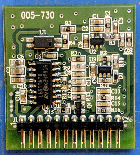
A2C: PFC_STOP: This is the output of pin 9 of a L6599AT controller inside the power supply. This controller is responsible for the HV supply. This output will go low (0V) when the supply is not running or when it has been shutdown by the protection circuit.
For reference, this is the HV control PCB from the power supply:

