I’m running a bit behind on my self-imposed schedule, but you’re all Glowforge owners - you should be accustomed to such things.
I’ve decided to take the time to do a few things while making the revisions.
First: I’m converting all my design files to the latest beta of KiCad. I did the design work for the original prototype in an earlier beta for version 5. However, they changed the way they organized the library since then, and it screwed me all up.
Not a big deal, but it does mean that I am starting the whole schematic capture from scratch.
Second: I’ve learned quite a bit about the design and functioning of the Glowforge while bringing up the first prototype. There were many areas where I just followed what Glowforge did on their control board simply because I wasn’t sure why they did it. With my newfound understanding, I’m making some significant changes (detailed a bit more below).
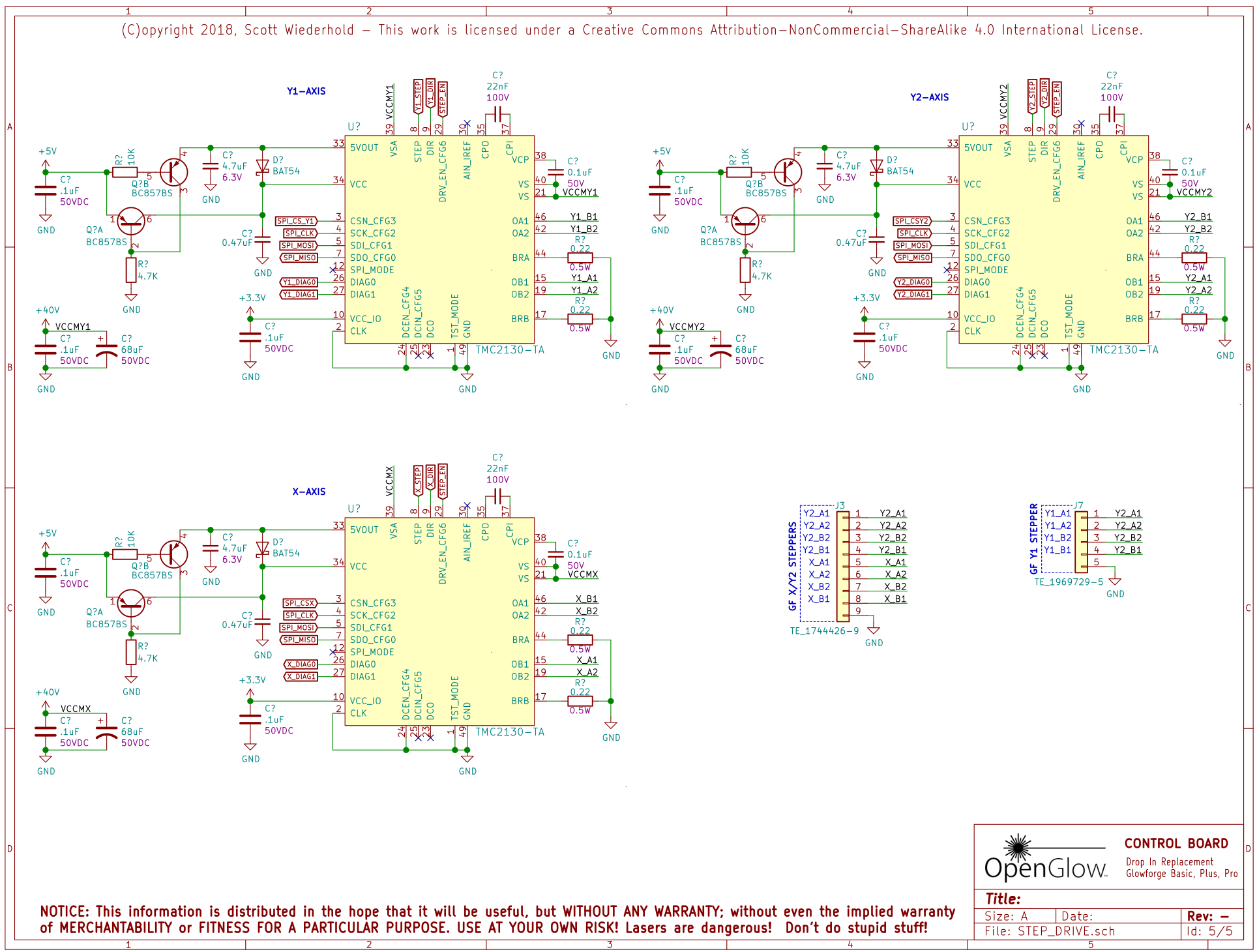
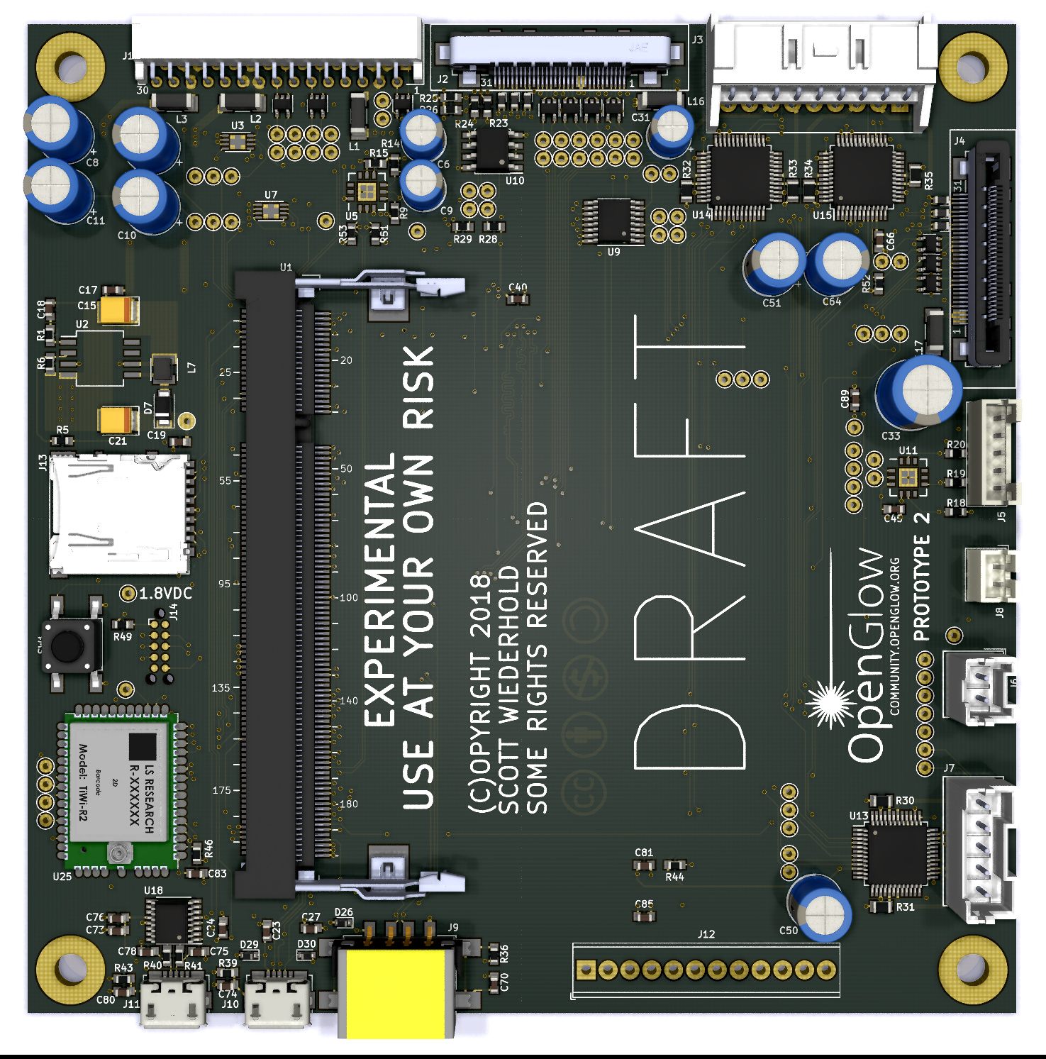
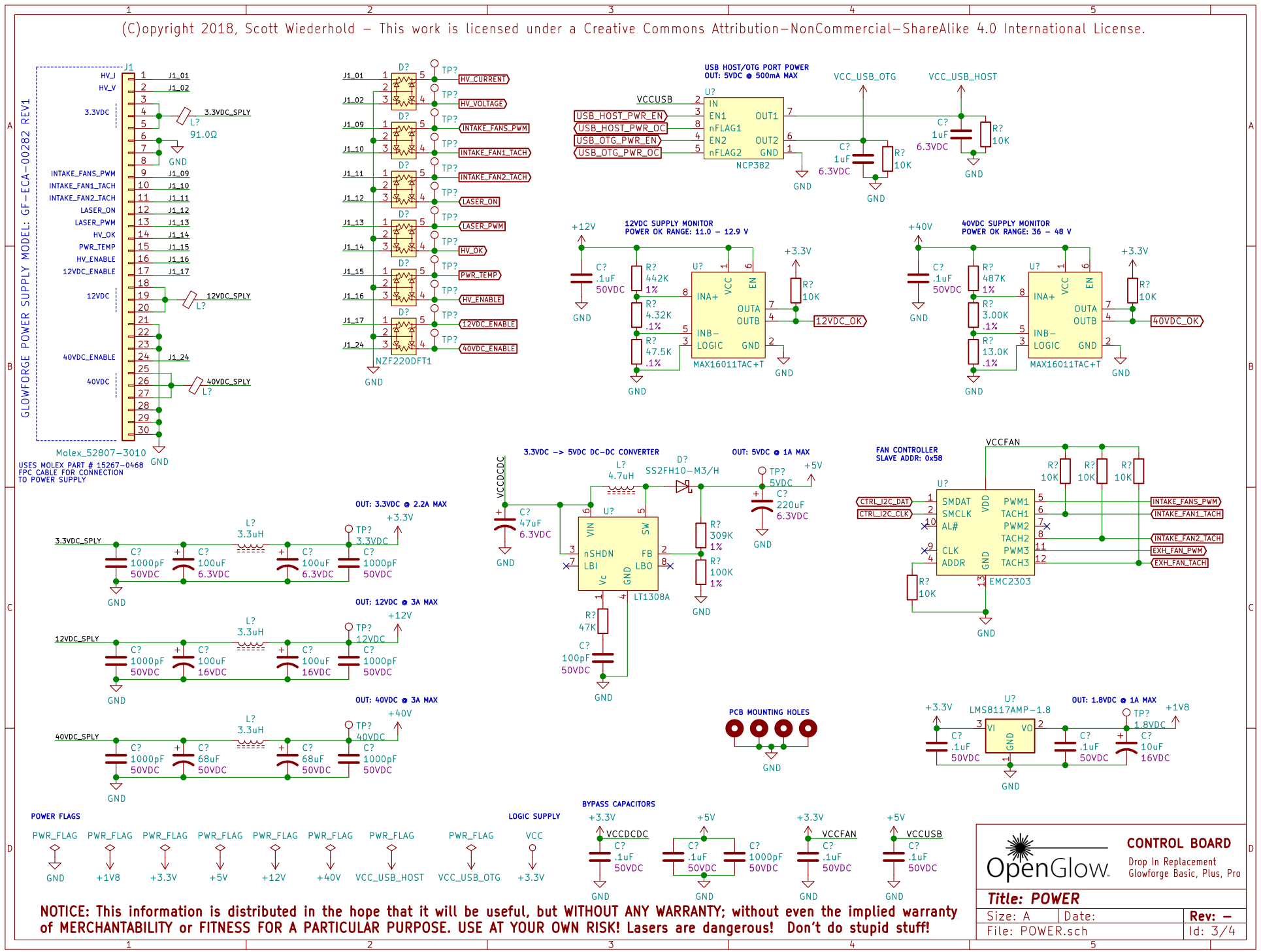
Below are a couple shots of the new draft of the design. Please note, these are not fully vetted and shouldn’t be relied upon as accurate.
POWER SECTION:
LID / INTERCONNECTION INTERFACES:

Notable Changes:
-
Fans: Glowforge uses the iMX6’s PWM outputs to drive the fans, and input pins on iMX6 to read the fan tachometers. The problem with this is that the fan tachometers generate a processor interrupt twice per fan revolution per fan. That’s over 41,000 interrupts per second during normal operation, just to read the RPM of the fans. Insane! I am using a dedicated hardware fan controller instead. It costs less than $1.50, and communicates over the I2C bus. It also has some nifty features (including automatic speed control), giving users some more things they can tweak.
-
Analog to Digital Conversion: Glowforge used a PIC microcontroller to convert the analog voltages coming from the various temperature, infrared, and high-voltage sensors to digital values. The PIC is cheap, also around a $1.50, but has the disadvantage that it needs to be programmed. In a production product, that’s not a big deal. In a small batch hobby device like the OpenGlow, it adds complexity that most users will probably not like. Plus, you need to have a programmer (an extra couple hundred dollars). Instead, I’ve replaced this with a dedicated ADC with an I2C interface. It costs about a $1 more than the PIC.
-
Button LED Driver: The downfall to removing the PIC is that it was also used to drive the LED’s in the button. I’ve replaced that with the same driver used for the fans, as it has 3 PWM outputs that are easily programmable via I2C.
To those with a background in electronics, take a look and tell me what I’m doing wrong.
Feel free to ask what anything in there does. If I know ( ![]() ), I’ll pass on the knowledge.
), I’ll pass on the knowledge.
I’ll post more design details on this thread as I complete them.