There are three I2C buses on the Glowforge. Only two of these are in use.
If you have console access to your unit, you can see what is attached to them:
root@gf-abc-123:/# i2cdetect -y 0
     0  1  2  3  4  5  6  7  8  9  a  b  c  d  e  f
00:          -- -- -- -- -- -- -- -- -- -- -- -- --
10: -- -- -- -- -- -- -- -- -- -- -- -- -- -- 1e --
20: -- -- -- -- -- -- -- -- -- -- -- -- -- -- -- --
30: -- -- -- -- -- -- 36 -- -- -- -- -- -- -- -- --
40: -- -- -- -- -- -- -- -- -- -- -- -- -- -- -- --
50: -- -- -- -- -- -- -- -- -- -- -- -- -- -- -- --
60: -- -- -- -- -- -- -- -- -- -- -- -- -- -- -- --
70: -- -- -- -- -- -- -- --
root@gf-abc-123:/# i2cdetect -y 1
     0  1  2  3  4  5  6  7  8  9  a  b  c  d  e  f
00:          -- -- -- -- -- -- -- -- -- -- -- -- --
10: -- -- -- -- -- -- -- -- -- -- -- -- -- -- -- --
20: -- -- -- -- -- -- -- -- -- -- -- -- -- -- -- --
30: -- -- -- -- -- -- -- -- -- -- -- -- -- -- -- --
40: -- -- -- -- -- -- -- -- -- -- -- -- -- -- -- --
50: UU -- -- -- -- -- -- -- -- -- -- -- -- -- -- --
60: -- -- -- -- -- -- -- -- -- -- -- -- -- -- -- --
70: -- -- -- -- -- -- -- --
root@gf-abc-123:/# i2cdetect -y 2
     0  1  2  3  4  5  6  7  8  9  a  b  c  d  e  f
00:          -- -- -- -- -- -- -- -- -- -- -- -- --
10: -- -- -- -- -- -- -- -- -- -- -- -- -- 1d 1e --
20: -- -- -- -- -- -- -- -- -- -- -- -- -- -- -- --
30: -- -- -- -- -- -- 36 -- -- -- -- -- -- -- -- --
40: -- -- -- -- -- -- -- 47 48 -- -- -- -- -- -- --
50: -- -- -- -- -- -- -- -- -- -- -- -- -- -- -- --
60: -- -- -- -- -- -- -- -- -- -- -- -- -- -- -- --
70: -- -- -- -- -- -- -- --
Note: I unloaded the Glowforge drivers before running the above commands. If the drivers are loaded, most of these will report “UU”, which means they are being controlled by the driver.
Bus Descriptions
Bus 0x00: Lid - 400kHz
This bus runs to the LID.
- Device 0x1E: Lid accelerometer (NXP LIS2HH12 - datasheet)
- Device 0x36: Lid camera (OmniVision OV5648 - you’ll have to find the datasheet yourself. It’s proprietary. A little Google goes a long way…)
Bus 0x01: HDMI - 100kHz
This is unused in the Glowforge, and likely a relic from previous hardware they were developing on. This bus could be harnessed for external adapter board purposes…
- Device 0x50: HDMI EDID Slave Address
Bus 0x02: Control / Interconnect / Head - 100kHz
This bus connects to devices on the Control, Interconnect and Head PCB’s. To reach the Interconnect and Head PCB’s, it utilizes an I2C bus extender, which is detailed below.
- Device 0x10: Head MCU Bootloader. Only active when MCU is in bootloader mode.
- Device 0x1D: Control PCB accelerometer (NXP LIS2HH12 - datasheet)
- Device 0x1E: Head PCB accelerometer (NXP LIS2HH12 - datasheet)
- Device 0x36: Head camera (OmniVision OV5648)
- Device 0x47: Head PCB MCU. Most head functions are controlled via this device. (See the source for my kernel-module-glowforge fork for more details.)
- Device 0x48: Interconnect temperature sensor (NXP LM75B - datasheet)
Interconnect / Head Bus Extender
To extend the I2C bus over the long distances to the Interconnect and Head PCB’s, the Glowforge uses PCA9600 (datasheet) bus extenders. The Glowforge implementation follows the recommendations in the datasheet. It essentially is this:
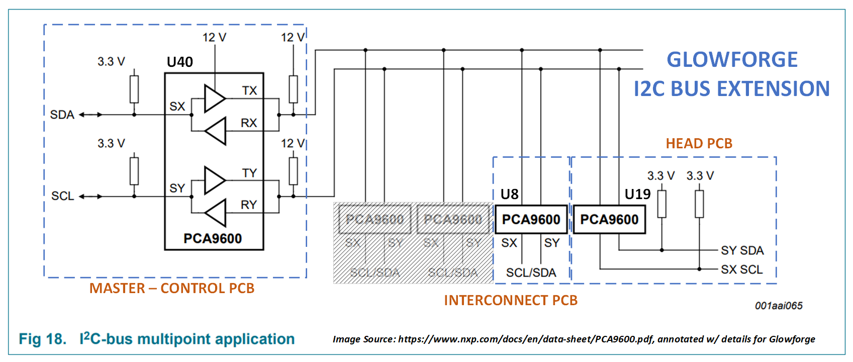
The I2C data and clock lines are buffered and converted from 3.3V to 12V before being sent over the long flat ribbon cables that separate the boards, then buffered and converted back to 3.3V on the other end.
Test Points
Control PCB
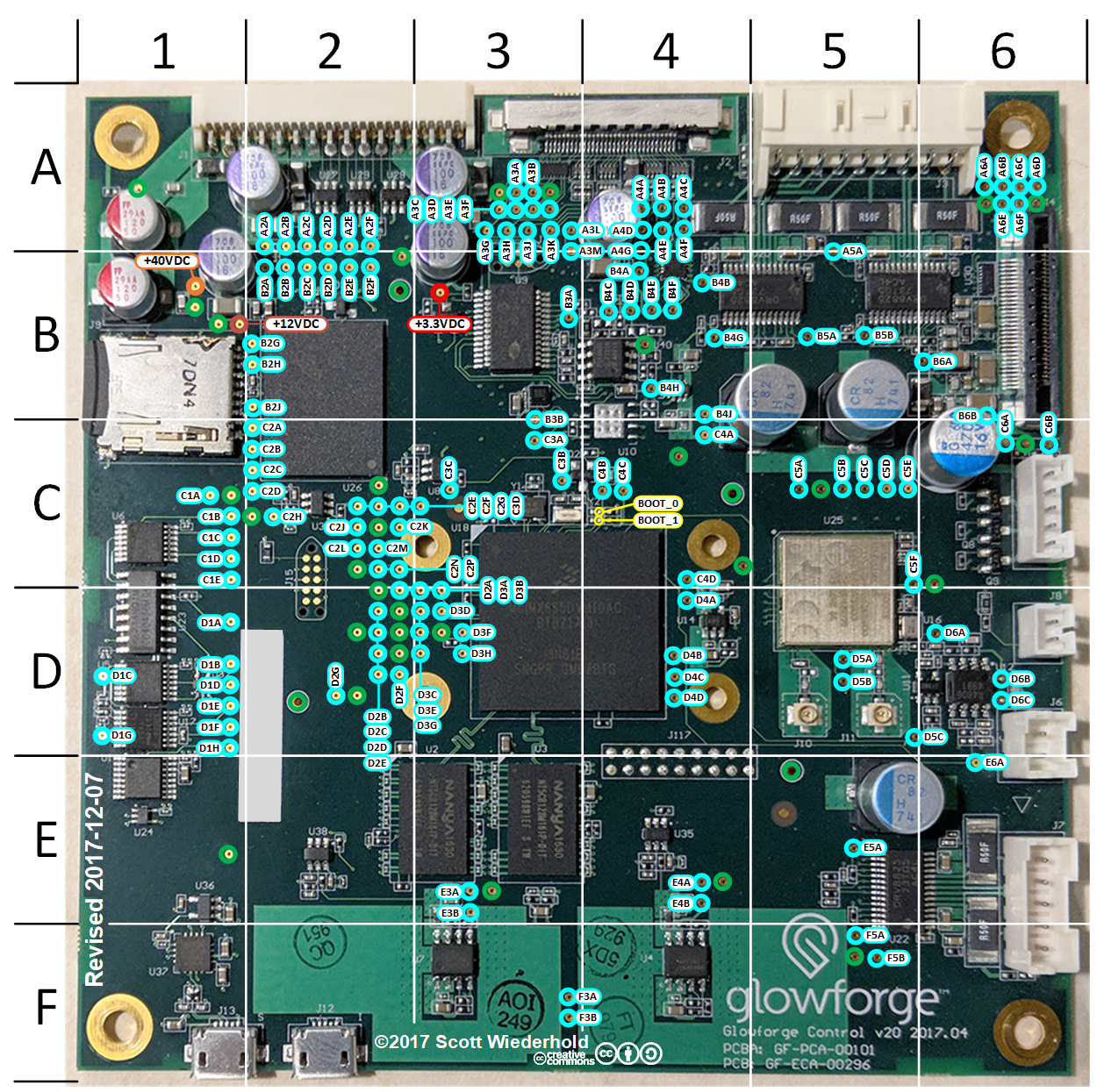
- Lid Bus:
TP-C6A: I2C-0 SDA
TP-C6B: I2C-0 SCL - HDMI Bus (unused)
TP-D3G: I2C-1 SDA
TP-D3E: I2C-1 SCL - Control / Interconnect / Head Bus
U40: PCA9600 located at grid C4
TP-B4H and U40 pin 1: I2C-2 SDA (3.3V level)
TP-B3A and U40 pin 7: I2C-2 SCL (3.3V level)
TP-B4D and U40 pin 3: I2C-2 SDA (12V level)
TP-B4C and U40 pin 5: I2C-2 SCL (12V level)
Interconnect PCB
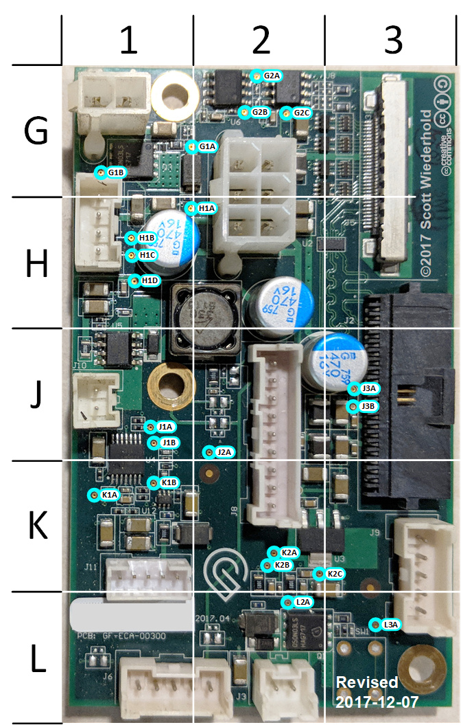
- Control / Interconnect / Head Bus
U8: PCA9600 located at grid G2
U8 pin 1: I2C-2 SDA (3.3V level)
U8 pin 7: I2C-2 SCL (3.3V level)
TP-J3B and U8 pin 3: I2C-2 SDA (12V level)
TP-J3A and U8 pin 5: I2C-2 SCL (12V level)
Head PCB

- Control / Interconnect / Head Bus
U19: PCA9600 located at grid T2 (underside of PCB)
TP-P2E and U19 pin 1: I2C-2 SDA (3.3V level)
TP-P2F and U19 pin 7: I2C-2 SCL (3.3V level)
U19 pin 3: I2C-2 SDA (12V level)
U19 pin 5: I2C-2 SCL (12V level)