So I am out of warranty, the wheels on the head assembly are an odd size as I have not been able to find them online. Has anyone had to replace those 4 wheels and what sizes did you go with? I do not want to buy the whole assembly from glowforge directly.
Unless someone here can identify the size and what they are called in industry, you are probably better off just buying the assembly. From the pictures I’ve seen they would probably be pretty easy to machine from Delrin or aluminum stock but the cost for short run would be pretty high and having a machinist make just 4 would easily be more than the head assembly, especially if he/she has to figure out the measurements.
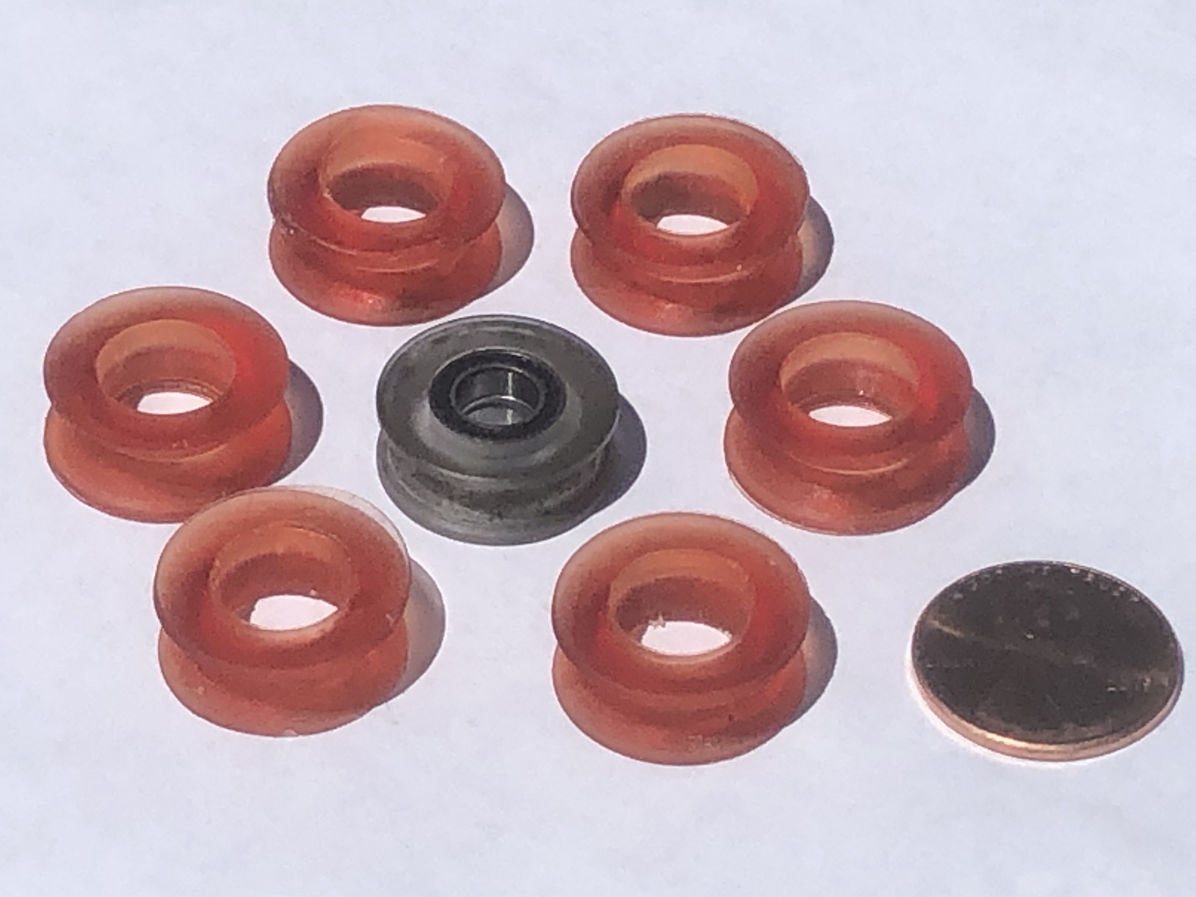
They look to be pretty standard polycarbonate v-wheels.
The rear wheels seem easier to find. They have an OD of 23.90 mm. I measure the ID of the bearing to be 6 mm, but every one I found online says 5 mm, so that might be the spec. This part looks like a possible replacement.
The front wheels are little harder to track down. I measure them of having an OD ~18 mm. Closest I have found is this one, with an O.D. of 15.23 mm. I can get a measurement close to that if really squeeze down on my calipers.
2 Likes
The rear wheels on the carriage are spring loaded and I just removed the carriage and measured the travel of those mounts, and there is very little wiggle room (maybe a couple of mm) for both larger and smaller diameter wheels, unless you were willing to Dremel a couple of mm from the slots the wheel mounts travel in.
Hi, I’ve been sporadically following Openglow for a couple months. I bought a second-hand unit locally, and it’s been great. But I know the day will come when it will break down, and I have no warranty, so I am very interested in this project overall.
I helped a few people over on the manufacturer’s site to design a 3D-printable replacement for the front wheels on the carriage. I haven’t installed these on my own Glowforge, because my wheels aren’t broken, but maybe you can use these…
ReplacementGantryWheel_v4.zip (32.5 KB)
I have printed them in both PLA and also UV-resin. I haven’t found an exact replacement for the original bearing, but you can use a pair of 6x10x3mm MR106-ZZ bearings. I found they are a tight fit for the bearings, so the center of the printed wheel may need to be gently persuaded with a drill bit to get the bearings to fit.
Since this is my first post here, it’s not letting me attach the .zip file with the STL, but I will add it once I have more privileges. In the meantime, PM me if you are desperate.
3 Likes
Thanks for the info!
These seem really hard to track down. I have a hard time believing that they would have had these made just for them, but I’ve been surprised before.
2 Likes
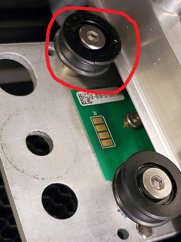
Yeah, it is strange. I designed this part because there has been a rash of posts from people with new machines having wheel failure within the first month or so of ownership. The problem seems to be limited to a recent batch of machines with black plastic wheels, not the clear ones like the original in the center of the photo.
From comments over there, everybody seems to think these wheels should be available somewhere, but nobody could provide specs or a link. Even finding a bearing that matches the original part was, in my experience, strangely impossible.
Nothing an allen wrench and a pair of calipers couldn’t solve.
Thanks for the upgrade! Here’s my latest STL file; if anyone tries it, let me know how it works out.
ReplacementGantryWheel_v4.zip (32.5 KB)
3 Likes
Do you have or might be able to create a neutral format CAD file for that part, say a STEP file? That looks very easy to machine, but STL files are not very compatible with most CAM programs.
Hmmm… good question.
I had intended this part to be 3D printed, so STL is what I’ve always considered to be a “neutral” format to most slicer programs. But you’re not the first person who’s suggested machining these.
I designed it in OpenSCAD, which doesn’t support .STEP as an output format. I am sure the STL could be loaded into TinkerCAD or equivalent and then exported to .STEP format, but I’m not really equipped to do that easily.
If I can figure out a conversion path, I’ll do it. If someone else beats me to it, please feel free to share the file back here.
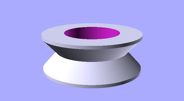
The part geometry (as I’ve interpreted it) is pretty simple. It’s basically a couple of opposing cones with the center bored out for a bearing. The original part has a couple tiny features that I didn’t model exactly. I was mainly concerned with getting the effective diameter of the wheel to match the original, and I was also trying to strengthen a couple of thin points.
If the part design is as simple as it looks, accurate dimensions of the features should be enough to replicate the part in parametric CAD. I’m not an OpenSCAD user but a brief search suggests that it may use a text file to generate the the part geometry. If that assumption is correct the part dimensions may be discernible from the part file itself. Does that make sense?
I’d kind of thought that a machined part may be more robust than a 3D-printed one as the machined part wouldn’t have the layers that might de-laminate with extended use. Then too, more materials are available for fabrication by machining so there may be advantages there.
1 Like
Totally. I calipered the original wheel and have all the critical dimensions. I’m running ot the door now, but I’ll post dimensions, etc. shortly, when I have time to document it more clearly.
The quick dimensions (in millimeters) are:
wheel_width = 6.8;  // wheel width, in mm
wheel_od = 17.9;    // wheel od - truncated to fit inside this cylinder
wheel_groov_od = inch / 2;  // wheel diameter at bottom of V (Seems slightly less than 13mm, so I'll go with 1/2")
bearing_od = 10;    // Bore for bearing: 10mm
I initially modeled the inside of the V as a straight 45-degree slope, but after a few design iterations it is not. The original wheel has a small ledge inside the groove that I didn’t model, which could impact the effective diameter slightly.
One word of warning, I don’t know that anybody has actually installed these on a Glowforge, so this design is untested at the moment. I did 3D print a few sets and bought some bearings to fit, so I have a set I plan to pop into my machine just for chuckles. I should probably verify that the wheels fit before you do too much derivative work.
It should be pretty close, though, so any adjustments will be minor.
1 Like
Ok, here is a more detailed breakdown of how I constructed this part.
I removed the wheel from my laser and calipered the dimensions. I went through a few iterations to fine-tune some dimensions where I could discern a difference between the original and my 3D printed prototypes.
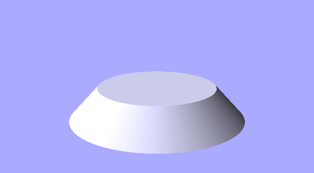
First I started with a truncated cone:
(diameter at base = 18.9mm, diameter at top is 12.7mm, height is 3.4mm)
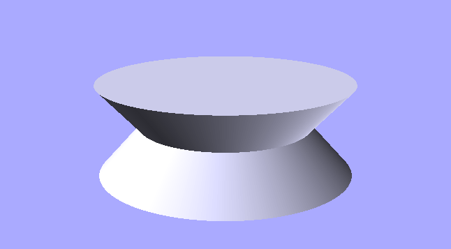
Then I added a mirrored copy of this cone on top:
(height of assembly is 6.8mm, to match the measured wheel width)
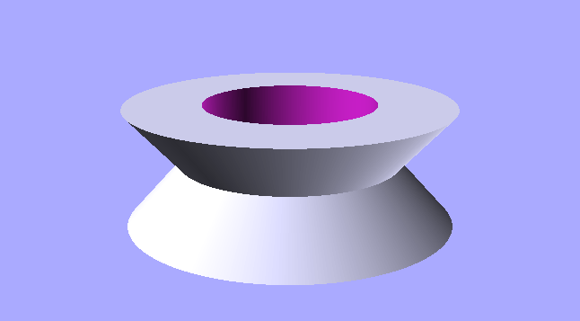
I bored out the center to accommodate the bearing:
(bore is 10mm)
And then I truncated the outside to match the outermost dimension of the original: (Not strictly necessary)
(outer diameter of bounding cylinder is 17.9mm)
Finally, here is the complete OpenSCAD script:
//
//  Replacement Glowforge Gantry Carriage Wheel
//

$fn = 360;  // Set angular resolution of output
inch = 25.4;  // millimeters / inch conversion

wheel_width = 6.8;
wheel_od = 17.9;
wheel_od2 = wheel_od + 1;
wheel_groove_od = inch / 2;
bearing_od = 10;

module wheel()
{
    translate([0,0,wheel_width/2])
    intersection()
    {
        difference()
        {
            union()
            {
                rotate([180,0,0])
                translate([0,0,-wheel_width/2])

                cylinder(d1=wheel_od2, d2=wheel_groove_od, h=wheel_width/2);

                translate([0,0,-wheel_width/2])
                cylinder(d1=wheel_od2, d2=wheel_groove_od, h=wheel_width/2);
            }

            cylinder(d=bearing_od, h=1000, center=true);
        }

        cylinder(d=wheel_od, h=1000, center=true);
    }
}

wheel();
Here’s what I came up with after seeing the first of your last two posts above. Does this look at all close? Note that I put a small chamfer on the hole edges and the outside edges of the wheel.
Gantry Gantry Wheel Draft.pdf (98.0 KB)
I see now that I added a 2mm flat at the bottom of the vee that probably shouldn’t be there and will fix that once I see your comments.
1 Like
I don’t see the chamfer indicated on the bearing borehole, but that would be a good idea to make it easier to press the bearing. (I do see that on the outer edge.)
The 2mm flat may be a bit too much, but not a bad idea. I added something similar to one of my design iterations when I was concerned about the strength of the part at the bottom of the V, but I ultimately took it out and the UV resin printed part seems to be strong enough without it. I didn’t caliper the rail this wheel rides along, which would tell how far down into the groove the wheel actually sits, but I would just be careful not to make your (2mm) flat wider than the rail. The wheel should self-center vertically when it sits against the rail. The 12.7 (1/2 inch) diameter was my best estimate of the very bottom of the groove. I did not intend for the flat to make contact with the rail.
For a 3D-printable part (without supports) I was trying to avoid going much beyond a 45-degree slope inside the V, but for a machined part this would not be a concern.
I did mine by taking 0.25mm off the bottom of the groove by incorporating a cylinder 0.5mm larger diameter than the bottom of the V. It looked like this:
Sorry got busy and just found time to reply.
First off, I don’t have a Glowforge laser having gotten refunded for my pre-order a couple years ago and put the money toward a different laser. Consequently I have no way to measure the wheels myself. Second, I’d toyed with the idea of machining a few wheels up in Delrin or some other engineering plastic for someone to test but that’s not really feasible without a known good drawing or a sample wheel to dimension myself. Being retired, I have a bit of free time on my hands and that looks like a pretty simple part to machine. If anyone wants to send me a sample, DM me and I’ll provide contact info.
Mike
It’s a generous offer.
My experience with this wheel design is that there isn’t actually that much real demand for them. I originally modeled it when a bunch of people were complaining about slow response from GF Support and rumors about long lead times for replacements. But when I offered to 3D print them and mail them out to whomever needed them - at no charge - I only got one request. And when I sent 4 wheels to that person, I heard nothing in reply until I asked. Then I was told that the GF replacements came and my replacements were sitting around as spares in case of a future failure.
So, to this date I am unaware of anybody getting desperate enough to even install these on their cutter. I figured that enough people in this hobby would be able to print wheels if they needed them, and a full set of these can be printed in a matter of minutes.
There has been plenty of speculation about whether a 3D printed wheel would be strong enough for this application, but no empirical data in either direction. I don’t doubt that a machined wheel would be more durable, I just don’t know if it is worth the effort or materials to make them.
For my part, my original wheels are back on my Glowforge and I don’'t have any genuine spares to send out to you. Maybe someone here has a broken or spare-parts machine?
1 Like
No worries - the offer still stands if anyone wants to take advantage.
I suspect that the demand for an alternative wheel is there but dissipates quickly when GF ships out replacements.
1 Like
Has anyone found a drop in replacement readily available online? I have a 3d printer but would prefer to buy some quality or even metal wheels.
I am looking for a suitable 6x19x7mm Deep V Groove guide rail/pulley wheel that goes on the TOP of the carriage, not underneath the gantry… does anyone have an idea of what will work?
On 07October, I found a crack in one of the front carriage wheels. Although c/s was quick to reply, and get an order set up, (I paid for two additional front carriage v-wheels, and an extra X-axis belt) the parts never were sent out (they were supposed to arrive 15Oct, but FedEx never picked up the package ). I contacted the same rep again (Maile), and she did up another order, but it’s been 3 days, and there’s been nothing more than an order confirmation done. No tracking number, nothing. I think I have about maybe 50 - 70 hours on my GF, and now it’s been down 2 weeks now, I’m missing out on Holiday orders, and since I have a Basic,. my warranty is about to expire in about 3 weeks. All communications with anyone from GF has stopped, and there is no movement on my original order, nor the new one. I’m beyond frustrated. $3-4K may not be alot of money to some people, but it’s a HUGE expenditure for me… right now, this machine is a VERY EXPENSIVE paperweight, and if my warranty is not extended because of no fault of my own, I’m definitely not going to be a happy camper. If GF is not going to send my parts, I at least want my money refunded, and I’ll find something that will at least get the carriage to do what it’s supposed to… I’m sick of GF’s ducking and dodging, all of a sudden… I want my parts so I can try to make some money, or I want a refund of what I paid to get this run-around.
A plastic, like Delrin or acetal might be better. Metal wheels might wear the tails too much and replacing them would be a lot harderto do than the rails.