UPDATE: I’ve posted an easier way to get serial access here. But, if you like a challenge, feel free to try the method described below.
Back in January 2018, Glowforge announced they were no longer populating the components required for console connectivity. If you’re one of the unlucky ones that received a later production unit and you want console access, this post is for you.
What you’ll need:
- A decent soldering iron
- Very thin rosin core solder
- Liquid solder flux
- Solder flux cleaner
- De-soldering braid/wick
- A magnifying glass
- USB microscope
- Surface mount tweezers
- Steady hands
- Lots of patience
You’ll also need the following electronic components:
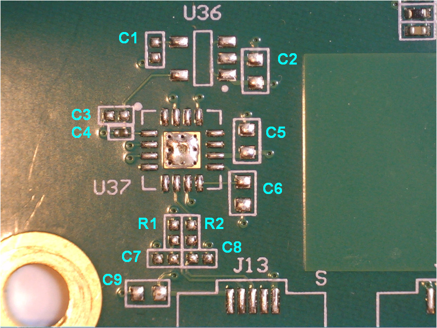
- U36: TPS79918DDCR (Mouser P/N: 595-TPS79918QDDCRQ1)
- U37: FT230XQ-R (Mouser P/N: 895-FT230XQ-R)
- C1, C3: 2.2uF/6.3V 0402 (Mouser P/N: 80-C0402C225K9P)
- C2, C5, C6, C9: 0.1uF/50V 0603 (Mouser P/N: 80-C0603X104K5R)
- C7, C8: 47pF/16V 0402 (Mouser P/N: 80-C0402C470J4G)
- R1, R2: 27 ohm 1/16W 1% (Mouser P/N: 603-RT0402FRE0727RL)
- C4: Not populated
- J13: USB Micro B (Mouser P/N: 798-ZX62-B-5PA33)
Installation:
If you haven’t worked with surface mount components before, you are in for a real treat. They are very (and I do mean very) tiny. Order a bunch of extra parts, because you will lose a bunch of them. The main tips I can give are to keep your soldering iron tip clean, and use lots of flux. Other than that, it just takes practice. (I won’t go into the finer points here - you can find many resources on the Intertubes).
WARNING: You can permanently damage your control board if you do this wrong. You’ve been warned.
First, do yourself a favor and use some solder wick to remove the stenciled on solder from the production process. This gives you a flat surface to work from:

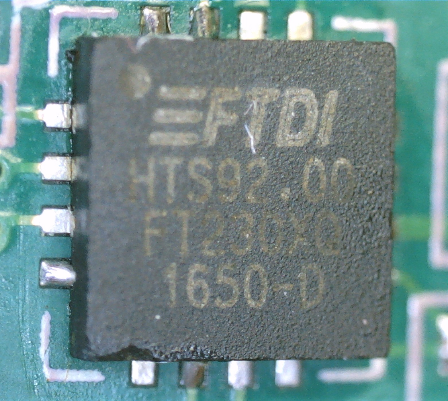
I like to start with the biggest pain in the a**, which is the FTX230 in a QFN package. The approach that works for me is to solder one corner in first, and verify alignment. Alignment on this sucker is critical. Align the little dot in the corner of the chip with the upper right, as oriented in the photos:
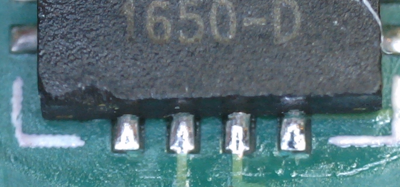
Once you get them all aligned (this is where the USB microscope comes in handy) flux it up and solder all the remaining pins. This will take time, and you’ll probably bridge a few of them (solder wick will clean that up). After you think you have it right, clean all the flux off and inspect all the joints closely.
They should all look like this:
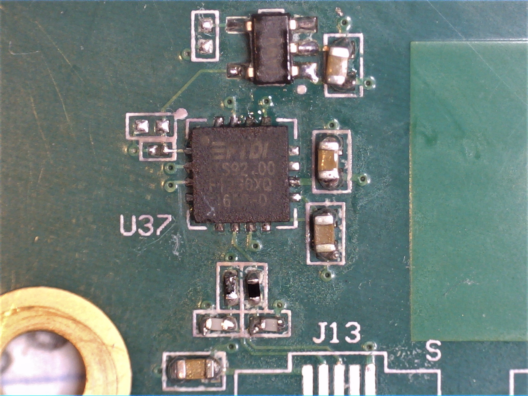
Move on to the other parts. You don’t have to be perfect - just make sure there are no solder bridges shorting anything out, and the components are actually soldered to the pads. I’ve been doing this a long time, and mine still look like crap. Pretty isn’t always functional, but ugly often is:
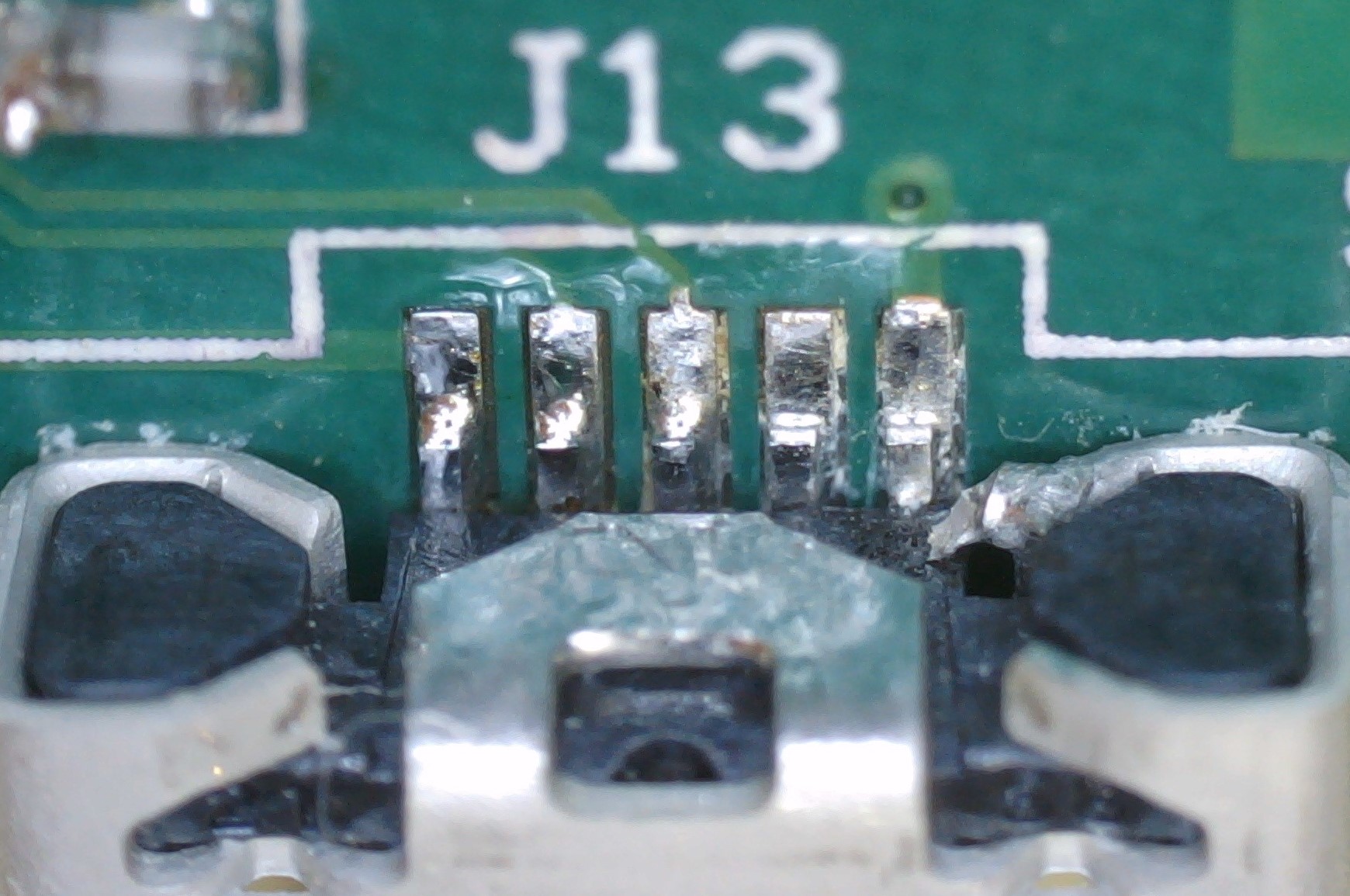
Take care when doing the USB connector. The leads are difficult to reach, and it is very easy to get solder bridges under there. The last pin on the right here has a spot that is a little too close for my comfort, and needed some clean up:
Once you’re done, clean off all the solder flux and do a full inspection with the USB microscope. After that, go ahead and connect it to the USB port to your computer. It is powered by the USB bus, and should be detected immediately by your computer as a USB serial port. If it doesn’t, start over.
You can now reinstall the board in your Glowforge, attach the USB cable, and power it up. Full instructions for connecting to the console port can be found here.
Happy hacking!